4 layers96 × 96 mm

 StarGate01/power-extender5
Hardware and software for a power and IO extension PCB with current monitoring and I2C interface.
Power extender is an open-source printed circuit board by StarGate01, from the StarGate01/power-extender repository on GitHub, published under the MIT licence. It is a 2-layer board of 90 × 71 mm with 78 parts on 70 nets, routed with 485 tracks and 45 vias.
It is built around the CC6902SO-10A, ADS1115IDGS and PC817X2CSP9F, with the PCA9557PW, 1N4007F and PMBT3904 among its other parts. Its parts include 25 resistors, 11 ICs, 10 capacitors, 8 diodes and 8 connectors. It belongs with the home automation and IoT and sensors and measurement boards of this library.


Hardware and software for a power and IO extension PCB with current monitoring and I2C interface.
This project has been generously supported by PCBWay. Read more about this project and also my review of the manufacturing on my blog: Design And Assembly Of An I2C Relay PCB
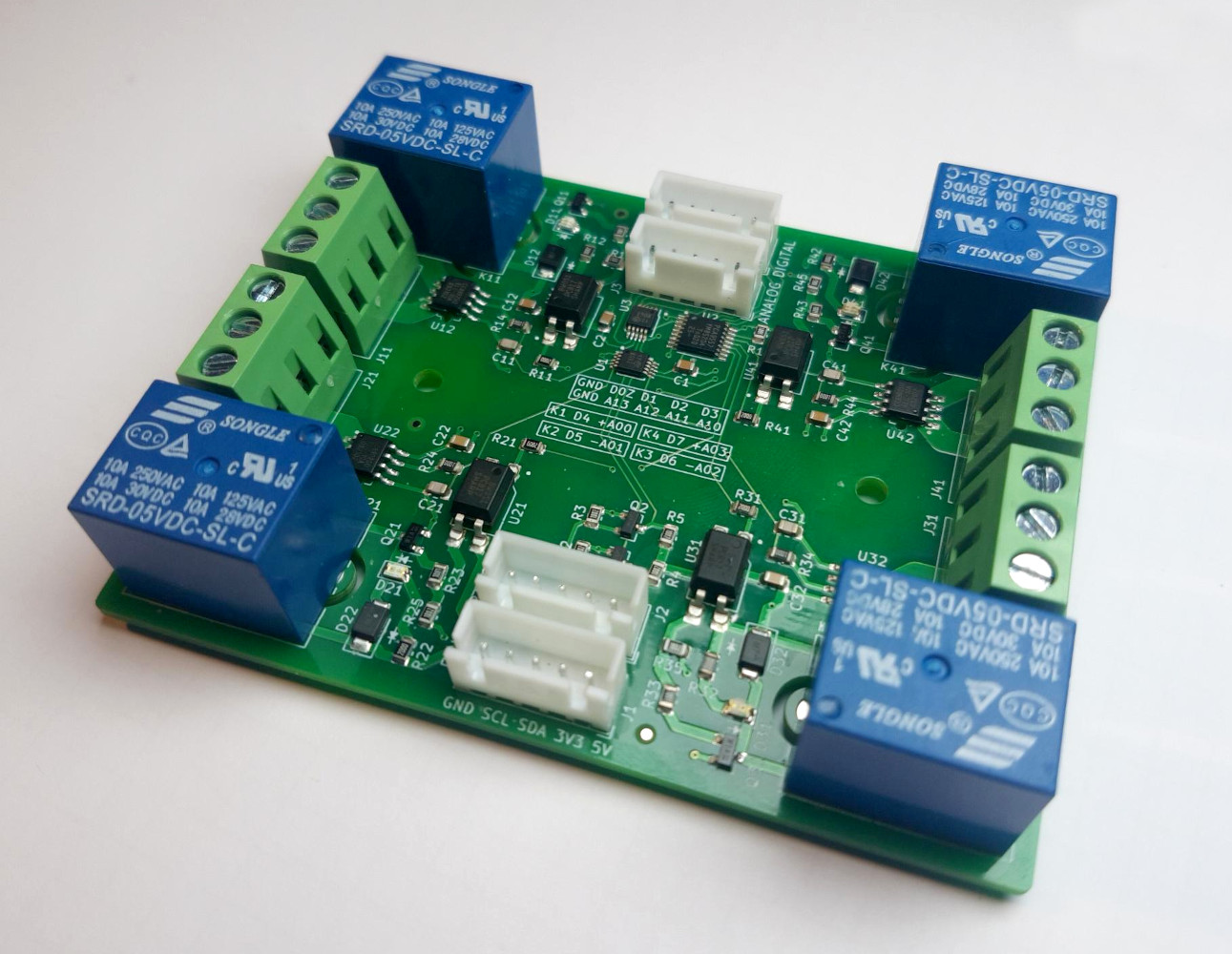
Use KiCad with my CustomComponents library to view and edit the hardware project, or download the fabrication files for PCB and/or PCBA manufacturing. I used KiBOM to generate the BOM. You can also download the complete schematics as PDF.
See the Arduino library documentation for usage with the Arduino framework. The library is also available on PlatformIO. Use Visual Studio Code and the PlatformIO plugin to edit the Arduino library and tests.
See the Raspberry Pi library documentation for usage with the Raspberry Pi Python 3 smbus framework.
5V and 3V3 pins
250mA @ 5V to actuate all four relays simultaneously30mA @ 5V standby current3V3 voltage level is only required for I2C level shifting if the I2C signal level is 3.3V instead of 5VRPI
PASS3.3V - 5V tolerant busSRD-05VDC-SL-C three-lead (NC - COM - NO) magnetic relays
CC6902SO-10A inductive current measuring IC connected across COMCOM - NO actuation2oz thick copper traces enable high currents10A, 250VAC, 110VDC7A @ 28VDC, 10A @ 125VAC, 7A @ 240VAC, inductive 3A @ 120VAC, 3A @ 28VDCPCA9557 8-channel GPIO port (I2C address: 0x18), logic level 0V | 5V
0Z - 3 connected to JST header DIGITAL4 - 70Z): 25mA sink, 20mA source per channel, max. total: 100mA sink, 85mA source0Z is high-impedance and open-drain (see datasheet for details)ADS1115 4-channel 16-bit ADC ports, voltage range 0V - 5V
0x48)ANALOG (I2C address: 0x49)10mA continuous input currentFor further specifications and ratings, all datasheets can be found in this repository.
Due to the inherent nature of magnetic relays, the inductive current measuring ICs and also the ADCs experience a measurement offset while the relays are energized. It is recommended to measure the actual load at a distance from the board, in order to obtain reference values. These reference values should then be used to compute an offset or function for each channel and amount of relays energized.
For no load (floating) using an Arduino Uno, the maximum absolute measurement offset was found to be about as follows.
| Amount of relays energized | Offset at energized channel | Offset at disabled channel |
|---|---|---|
| 0 | 0.05A | 0.05A |
| 1 | 1A | 0.7A |
| 2 | 1.5A | 1.3A |
| 3 | 2A | 1.8A |
| 4 | 2.4A | N / A |
Please note that these offsets are dependent on load and environmental factors.
17 unique parts, 60 SMT parts, 12 THT parts on a double-sided 90mm x 71mm PCB with 2oz copper finish.
Component cost per board: about $25 (Ignoring shipping, bulk discounts and changes in price over time).
| Item # | Designator | Quantity | Manufacturer | Manufacturer Part # | Description / Value | Distributor | Distributor part # | Package / Footprint | Type | Notes |
|---|---|---|---|---|---|---|---|---|---|---|
| 1 | C11, C21, C31, C41 | 4 | Any | TBD | CAP CER 100PF MAX. 5% MIN. 10V 0805 SMD | Any | TBD | SMD 0805 | SMD | |
| 2 | C1, C2, C12, C22, C32, C42 | 6 | Any | TBD | CAP CER 100NF MAX. 5% MIN. 10V 0805 SMD | Any | TBD | SMD 0805 | SMD | |
| 3 | D12, D22, D32, D42 | 4 | Shikues | 1N4007F | DIODE 1N4007 SMAF | LCSC | C110856 | SMAF | SMD | |
| 4 | D11, D21, D31, D41 | 4 | Everlight Elec | 17-21SURC/S530-A3/TR8 | LED RED 2V 0805 SMD | LCSC | C72037 | SMD 0805 | SMD | |
| 5 | J1, J2, J3, J4 | 4 | Any | TBD | CONN JST-XH PITCH-2.50MM VERTICAL MALE 5 PIN | Any | TBD | Through Hole | PTH | |
| 6 | J11, J21, J31, J41 | 4 | Ningbo Kangnex Elec | WJ128V-5.0-3P | CONN SCREW TERMINAL PITCH-5.0MM 3 PIN 20A | LCSC | C8270 | Through Hole | PTH | |
| 7 | K11, K21, K31, K41 | 4 | Ningbo Songle Relay | SRD-05VDC-SL-C | RELAY SEALED SENSITIVE 5V 10A | LCSC | C35449 | Through Hole | PTH | |
| 8 | Q1, Q2 | 2 | Shikues | BSS138 | MOSFET N-CH SOT-23-3 | LCSC | C112239 | SOT-23-3 | SMD | |
| 9 | Q11, Q21, Q31, Q41 | 4 | Nexperia | PMBT3904,215 | BJT NPN SOT-23-3 | LCSC | C8667 | SOT-23-3 | SMD | |
| 10 | R14, R24, R34, R44 | 4 | Any | TBD | RES 100 OHM MAX. 1% MIN. 1/8W 0805 SMD | Any | TBD | SMD 0805 | SMD | |
| 11 | R11, R12, R21, R22, R31, R32, R41, R42 | 8 | Any | TBD | RES 200 OHM MAX. 1% MIN. 1/8W 0805 SMD | Any | TBD | SMD 0805 | SMD | |
| 12 | R1, R13, R23, R33, R43 | 5 | Any | TBD | RES 1K OHM MAX. 1% MIN. 1/8W 0805 SMD | Any | TBD | SMD 0805 | SMD | |
| 13 | R2, R3, R4, R5, R15, R25, R35, R45 | 8 | Any | TBD | RES 10K OHM MAX. 1% MIN. 1/8W 0805 SMD | Any | TBD | SMD 0805 | SMD | |
| 14 | U1, U3 | 2 | Texas Instruments | ADS1115IDGSR | IC I2C 4 CH ADC VSSOP-10 | LCSC | C37593 | VSSOP-10 | SMD | |
| 15 | U12, U22, U32, U42 | 4 | Cross Chip | CC6902SO-10A | IC CURRENT SENSOR 5V 10A SOP-8 | LCSC | C350865 | SOP-8 | SMD | |
| 16 | U11, U21, U31, U41 | 4 | Sharp Microelectronics | PC817X2CSP9F | IC OPTOCOUPLER SMD-4 | LCSC | C66405 | SMD-4 | SMD | |
| 17 | U2 | 1 | NXP Semicon | PCA9557PW,118 | IC I2C 8 CH IO EXPANDER TSSOP-16 | LCSC | C141380 | TSSOP-16 | SMD |
| Qty | Value | Footprint | References |
|---|---|---|---|
| 8 | 10K | Resistor_SMD:R_0805_2012Metric | R2, R3, R4, R5, R15, R25, R35, R45 |
| 8 | 200R | Resistor_SMD:R_0805_2012Metric | R11, R12, R21, R22, R31, R32, R41, R42 |
| 6 | 100N | Capacitor_SMD:C_0805_2012Metric | C1, C2, C12, C22, C32, C42 |
| 5 | 1K | Resistor_SMD:R_0805_2012Metric | R1, R13, R23, R33, R43 |
| 4 | 100P | Capacitor_SMD:C_0805_2012Metric | C11, C21, C31, C41 |
| 4 | 100R | Resistor_SMD:R_0805_2012Metric | R14, R24, R34, R44 |
| 4 | 1N4007F | CustomComponents:D_SMAF | D12, D22, D32, D42 |
| 4 | CC6902SO-10A | CustomComponents:CC690XSO-XA | U12, U22, U32, U42 |
| 4 | LED | LED_SMD:LED_0805_2012Metric | D11, D21, D31, D41 |
| 4 | LOAD | TerminalBlock_Phoenix:TerminalBlock_Phoenix_MKDS-1,5-3_1x03_P5.00mm_Horizontal | J11, J21, J31, J41 |
| 4 | PC817X2CSP9F | CustomComponents:PC817X2CSP9F | U11, U21, U31, U41 |
| 4 | PMBT3904 | Package_TO_SOT_SMD:SOT-23 | Q11, Q21, Q31, Q41 |
| 4 | SRD-05VDC-SL-C | Relay_THT:Relay_SPDT_SANYOU_SRD_Series_Form_C | K11, K21, K31, K41 |
| 3 | Fiducial | Fiducial:Fiducial_1mm_Mask2mm | FID1, FID2, FID3 |
| 2 | ADS1115IDGS | Package_SO:TSSOP-10_3x3mm_P0.5mm | U1, U3 |
| 2 | BSS138 | Package_TO_SOT_SMD:SOT-23 | Q1, Q2 |
| 2 | MountingHole | MountingHole:MountingHole_3.2mm_M3 | H1, H2 |
| 1 | AUX ANALOG | CustomComponents:JST_XH_B5B-XH-A_1x05_P2.54mm_Vertical | J3 |
| 1 | AUX DIGITAL | CustomComponents:JST_XH_B5B-XH-A_1x05_P2.54mm_Vertical | J4 |
| 1 | IFACE PASS | CustomComponents:JST_XH_B5B-XH-A_1x05_P2.54mm_Vertical | J2 |
| 1 | IFACE RPI | CustomComponents:JST_XH_B5B-XH-A_1x05_P2.54mm_Vertical | J1 |
| 1 | PCA9557PW | Package_SO:TSSOP-16_4.4x5mm_P0.65mm | U2 |
The 77 most common of 78 parts.
It measures 90 × 71 mm and has 2 copper layers, 1.6 mm thick.
78 parts, built around the CC6902SO-10A, ADS1115IDGS, PC817X2CSP9F and PCA9557PW. The full list of its parts is on this page, with links to each part's symbol and footprint where PCBKit's library has them.
From the StarGate01/power-extender repository on GitHub, at the commit this page was made from: the board is hardware/power-extender.kicad_pcb. PCBKit opens the board in the browser, with nothing to install.
Its repository publishes it under the MIT licence: you may reuse it on that licence's terms (keep the author's notice, and for a copyleft licence share your changes alike).

Dominik-Workshop/resonant-converter
Resonant converter PCB, 60V -> 12V 10A

Takingo/Mypcb35
OmniCircuit AI is a local proof of concept for an autonomous PCB/PCBA design and manufacturing suite. The current implementation focuses on the ESP32-S3 + DWM3000 UWB Anchor example and establishes the architecture for:

nerdmaennchen/WattaVolt
this repository contains hardware + software for my custom PSU/bringup-tool/younameit


o-gs/dji-hardware-schematics
Community made schematics for the DJI drones and devices.

