
2 layers120 × 100 mm
Usb pd pico controller
flummer/sao-wall
Design for a SAO display PCB, power and control board
64 parts2CC-BY-SA-4.0

PCB Design made in KiCad for my automatic syringe pump project
Hw1 is an open-source printed circuit board by stanciugabriel, from the stanciugabriel/overture-pcb repository on GitHub. It is a 2-layer board of 92 × 50 mm with 65 parts on 74 nets, routed with 407 tracks and 106 vias.
It is built around the ESP32-C6-WROOM-1-N8, TPS54308DDCT and USBLC6-2SC6, with the ESDA25P35-1U1M, STL6P3LLH6 and ESDA25W among its other parts. Its parts include 20 resistors, 10 capacitors, 6 switches, 5 ICs and 4 diodes. It belongs with the ESP32 and RISC-V boards of this library.


Overture is a custom ESP32-C6 control board designed to drive a NEMA 17 stepper motor while handling NFC reading, a small display, and physical user inputs. Everything is powered through a single USB-C Power Delivery connection.
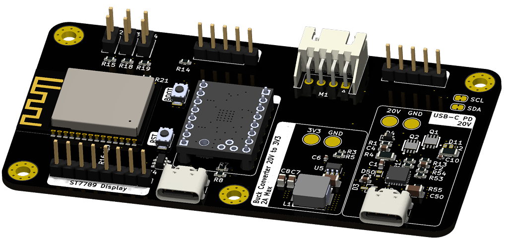
The board uses a dual USB-C port design to separate power and data.
To power the motor and board, plug a compatible USB-C PD charger into the main power port. The STUSB4500 handles the 20V negotiation automatically.
To flash the ESP32, use the secondary USB-C port. Note that the primary power port does not route data lines to the ESP32 and will not show up as a COM port on your machine.
The exports folder contains all the file for production:
| Qty | Value | Footprint | References |
|---|---|---|---|
| 6 | 10k | Resistor_SMD:R_0603_1608Metric | R6, R14, R15, R16, R18, R19 |
| 4 | 1uF | Capacitor_SMD:C_0603_1608Metric | C1, C2, C3, C4 |
| 4 | MountingHole_Pad | MountingHole:MountingHole_3mm_Pad_Via | H1, H2, H3, H4 |
| 4 | TestPoint | TestPoint:TestPoint_Pad_D3.0mm | TP_3V3, TP_20V1, TP1, TP4 |
| 2 | 100K | Resistor_SMD:R_0603_1608Metric | R10, R55 |
| 2 | 100k | Resistor_SMD:R_0603_1608Metric | R53, R54 |
| 2 | 100nF | Capacitor_SMD:C_0402_1005Metric | C6, C10 |
| 2 | 1k | Resistor_SMD:R_1206_3216Metric | R2, R4 |
| 2 | 33uF | Capacitor_SMD:C_0805_2012Metric | C7, C8 |
| 2 | 5.1k | Resistor_SMD:R_0603_1608Metric | R7, R8 |
| 2 | ESDA25P35-1U1M | hw1_footprint:TVS_ESDA25P35-1U1M | D11, D50 |
| 2 | STL6P3LLH6 | hw1_footprint:mosfetty | Q1, Q2 |
| 2 | SW_Push | hw1_footprint:SW_TS-1088-AR02016 | SW5, SW6 |
| 2 | USB_C_Receptacle_USB2.0_16P | Connector_USB:USB_C_Receptacle_GCT_USB4105-xx-A_16P_TopMnt_Horizontal | J1, J2 |
| 2 | ~ | Jumper:SolderJumper-2_P1.3mm_Bridged_RoundedPad1.0x1.5mm | JP5, JP6 |
| 1 | 100 | Resistor_SMD:R_0603_1608Metric | R13 |
| 1 | 100k | Resistor_SMD:R_0402_1005Metric | R3 |
| 1 | 22K | Resistor_SMD:R_0603_1608Metric | R11 |
| 1 | 22k | Resistor_SMD:R_0603_1608Metric | R5 |
| 1 | 3.3uH | hw1_footprint:IND-SMD_L7.2-W6.6_GPSR07X0 | L1 |
| 1 | 4.7k | Resistor_SMD:R_0603_1608Metric | R21 |
| 1 | 4.7uf | Capacitor_SMD:C_1206_3216Metric | C50 |
| 1 | 470 | Resistor_SMD:R_0603_1608Metric | R1 |
| 1 | 6.8uF | Capacitor_SMD:C_1206_3216Metric | C5 |
| 1 | ESDA25W | hw1_footprint:SOT65P210X110-3N | D3 |
| 1 | ESP32-C6-WROOM-1 | hw1_footprint:ESP32-C6-WROOM-1_edit | U6 |
| 1 | RotaryEncoder_Switch | Connector_PinHeader_2.54mm:PinHeader_1x05_P2.54mm_Vertical | SW1 |
| 1 | STUSB4500QTR | hw1_footprint:QFN-24-1EP_4x4mm_P0.5mm_EP2.65x2.65mm | U2 |
| 1 | SW_Back | Connector_PinHeader_2.54mm:PinHeader_2x01_P2.54mm_Vertical | SW2 |
| 1 | SW_Bolus | Connector_PinHeader_2.54mm:PinHeader_2x01_P2.54mm_Vertical | SW3 |
| 1 | SW_Settings | Connector_PinHeader_2.54mm:PinHeader_2x01_P2.54mm_Vertical | SW4 |
| 1 | Schottky | Diode_SMD:D_SOD-323 | D4 |
| 1 | Stepper_Motor | Connector_JST:JST_XH_S4B-XH-A_1x04_P2.50mm_Horizontal | M1 |
| 1 | TPS54308DDCT | hw1_footprint:SOT95P280X110-6N | U5 |
| 1 | USBLC6-2SC6 | Package_TO_SOT_SMD:SOT-23-6 | U4 |
| 1 | ~ | hw1_footprint:TMC2208_edit | U1 |
| 1 | ~ | Connector_PinHeader_2.54mm:PinHeader_1x05_P2.54mm_Vertical | PN532-Module1 |
| 1 | ~ | Connector_PinHeader_2.54mm:PinHeader_1x08_P2.54mm_Vertical | ST7789-Display1 |
The 63 most common of 65 parts.
flummer/sao-wall
Design for a SAO display PCB, power and control board

Accelerator6666/Yaesu-FT2D-USBC-charge
检查日期:2026-10-26;KiCad 10.0.7;目标板厂:嘉立创 JLCPCB;目标工艺:4 层 PCB + SMT 代贴片。

Suman-Gayen/USB-C-PD-Power-Supply-Board
Design a custom pcb for USB-C PD Power Supply Board

Justinorange/PCB-Compilation
A collection of custom PCB designs, prototypes, and lab projects built for research and experimentation.


PaulBichl/VibePCB-bench-psu
USB-C PD (20 V) powered bench supply, 2 independent channels, 1.6-16.6 V / 3 A each, constant voltage / constant current, designed with VibePCB.

rnanosaur/nanosaur-NX-shield
🦸 A nanosaur NX, need a super shield. The Nanosaur NX shield is here!

makeristic/STUSB4500_Breakout
KiCad USB-C Power Delivery sink breakout using STUSB4500, with STEMMA QT I2C, screw-terminal output and RGB indication. Work in progress.
It measures 92 × 50 mm and has 2 copper layers, 1.6 mm thick.
65 parts, built around the ESP32-C6-WROOM-1-N8, TPS54308DDCT, USBLC6-2SC6 and ESDA25P35-1U1M. The full list of its parts is on this page, with links to each part's symbol and footprint where PCBKit's library has them.
From the stanciugabriel/overture-pcb repository on GitHub, at the commit this page was made from: the board is hw1.kicad_pcb and its schematic hw1-backups/hw1-2026-04-24_154134/hw1.kicad_sch. PCBKit opens the board in the browser, with nothing to install.
Its repository states no licence, so its author keeps all rights: ask stanciugabriel before reusing the design.