

2 layers
Nanosaur NX shield
rnanosaur/nanosaur-NX-shield
🦸 A nanosaur NX, need a super shield. The Nanosaur NX shield is here!
28 parts1
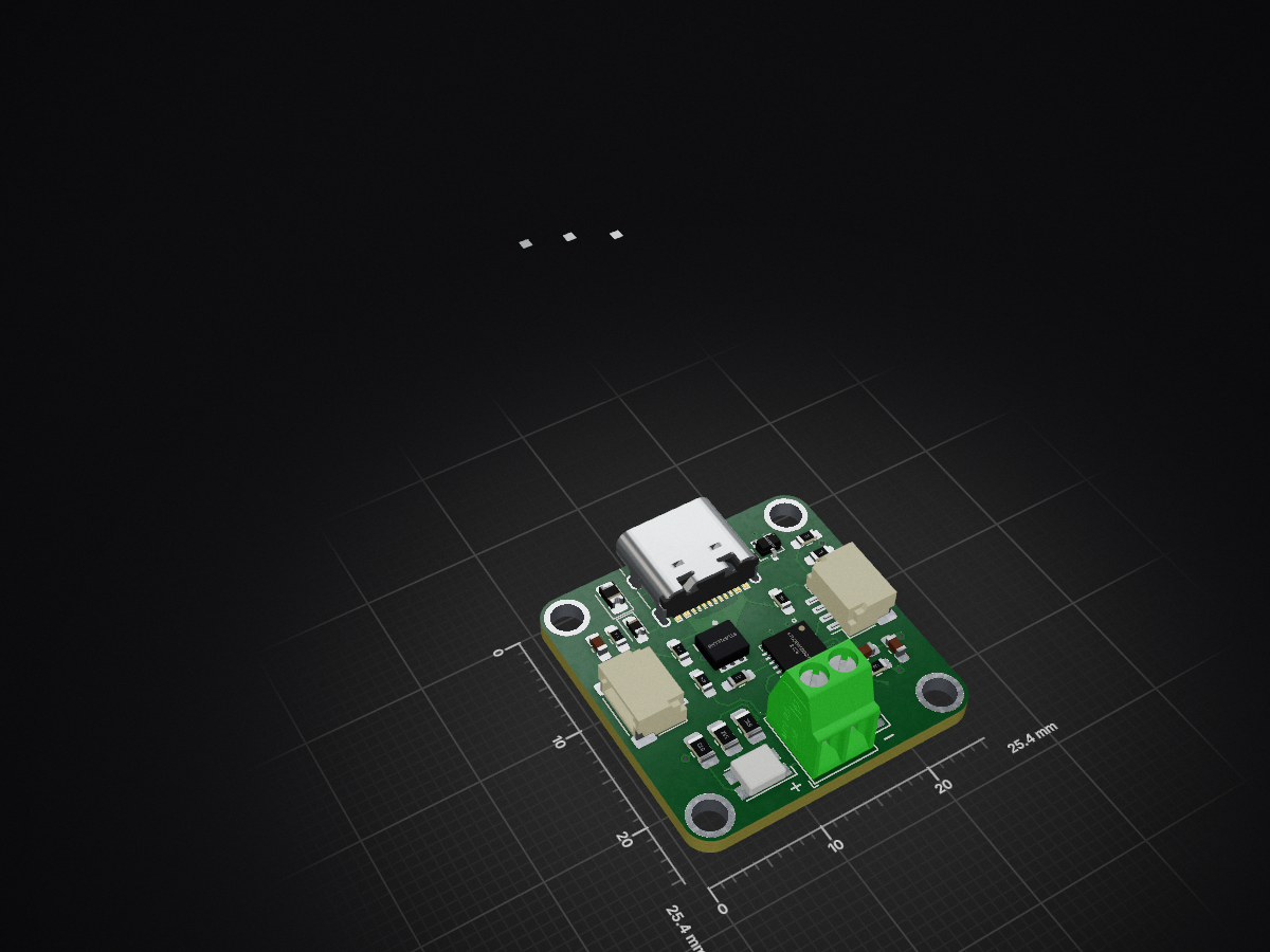
 makeristic/STUSB4500_Breakout
KiCad USB-C Power Delivery sink breakout using STUSB4500, with STEMMA QT I2C, screw-terminal output and RGB indication. Work in progress.
STUSB4500 Breakout is an open-source printed circuit board by makeristic, from the makeristic/STUSB4500_Breakout repository on GitHub, published under the CC-BY-4.0 licence. It is a 4-layer board of 25.4 × 25.4 mm with 34 parts on 30 nets, routed with 246 tracks and 48 vias.
It is built around the ASMB-MTB0-0A3A2, ESDA25W and STL6P3LLH6. Its parts include 11 resistors, 4 capacitors, 4 diodes, 4 connectors and 1 IC. It belongs with the power and interfaces and adapters boards of this library.


A KiCad design for a USB-C Power Delivery sink board built around the STMicroelectronics STUSB4500, with STEMMA QT I²C connectors, screw-terminal power output, and an RGB voltage indicator.
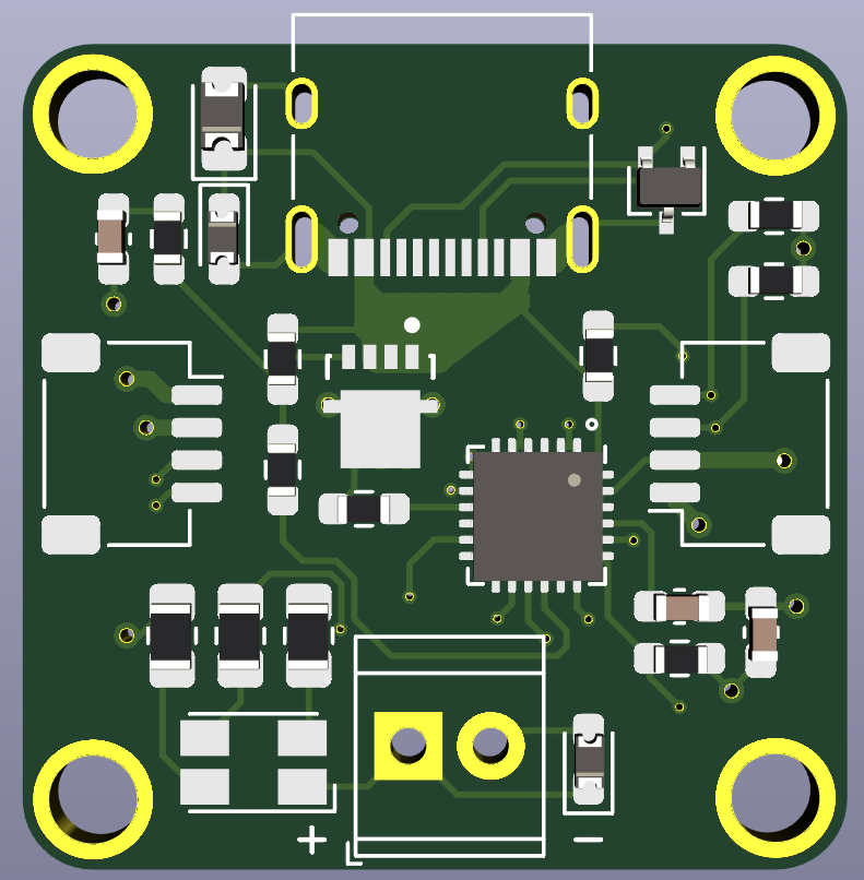
This is a hobbyist hardware project started in October 2020. The design history includes manufacturing preparation, and fabrication exports are included. The repository description has historically marked the project as work in progress; it does not record electrical validation results or a confirmed production revision.
Do not use the current source or included Gerbers/drill files for manufacture until the circuit issues are resolved. A source audit found VREG_2V7 tied to the host supply rail and an RGB indicator path from the negotiated supply to a low-voltage controller output. Those circuits require correction and review; the historical exports are not a validated release.
There is no standalone bill of materials, host firmware, or STUSB4500 configuration tool in this repository. Component values and footprints are recorded in the schematic.
STUSB4500_Breakout.pro in KiCad. The PCB records KiCad 5.1.7, and the schematic uses the legacy .sch format. Work on a copy when importing into a newer KiCad version..pretty footprints under the nickname Makeristic-KiCad-Library from that sibling directory. The design references its MOSFET, mounting-hole, and STEMMA QT logo assets. Keep the committed symbol cache with the schematic; it preserves historical symbol geometry and pin mapping.For nightly KiCad netlist checks, follow the audit's cache-only export procedure. Globally resolving the same legacy USB symbol in nightly 10.99.0 omitted the shield pin from the export; the audit records the exact conditions. This repository retains its original legacy design formats.
Use Issues for questions, build reports, or design corrections. Include the commit, KiCad version, and relevant schematic references; for pull requests, explain electrical changes and which exports you regenerated.
See also the Feather STM32WB55 board and the Makeristic repository collection.
The original work in this repository remains licensed under Creative Commons Attribution 4.0 International, as specified by the original README. See LICENSE for the full licence text. Attribute Michael Cutler / Makeristic and link to this repository when reusing the original design.
Vendor documents in docs/, third-party library elements embedded in the design, cached KiCad symbols, and third-party marks remain subject to their respective owners' terms; the project licence does not relicense those materials. KiCad symbols retain CC BY-SA 4.0 with the KiCad exception; the audit records their source version and provenance.

| Qty | Value | Footprint | References |
|---|---|---|---|
| 4 | MountingHole_Pad | Makeristic-KiCad-Library:MountingHole_2.7mm_M2.5_Pad_Small | H1, H2, H3, H4 |
| 3 | 10k | Resistor_SMD:R_0603_1608Metric_Pad0.98x0.95mm_HandSolder | R5, R6, R7 |
| 3 | 5.1k | Resistor_SMD:R_0805_2012Metric_Pad1.20x1.40mm_HandSolder | R9, R10, R11 |
| 2 | 1k | Resistor_SMD:R_0603_1608Metric_Pad0.98x0.95mm_HandSolder | R4, R8 |
| 2 | 1u | Capacitor_SMD:C_0603_1608Metric_Pad1.08x0.95mm_HandSolder | C2, C3 |
| 2 | ESDA25P35 | Diode_SMD:D_0603_1608Metric_Pad1.05x0.95mm_HandSolder | D3, D4 |
| 2 | LOGO | Makeristic-KiCad-Library:stemma_qt_logo | G***, G*** |
| 2 | STEMMA_I2C_QT | Connector_JST:JST_SH_SM04B-SRSS-TB_1x04-1MP_P1.00mm_Horizontal | J2, J3 |
| 1 | 100 | Resistor_SMD:R_0603_1608Metric_Pad0.98x0.95mm_HandSolder | R2 |
| 1 | 100k | Resistor_SMD:R_0603_1608Metric_Pad0.98x0.95mm_HandSolder | R1 |
| 1 | 100n | Capacitor_SMD:C_0603_1608Metric_Pad1.08x0.95mm_HandSolder | C1 |
| 1 | 22k | Resistor_SMD:R_0603_1608Metric_Pad0.98x0.95mm_HandSolder | R3 |
| 1 | 4.7u | Diode_SMD:D_0805_2012Metric_Pad1.15x1.40mm_HandSolder | C4 |
| 1 | ALERT | TestPoint:TestPoint_Pad_D1.0mm | ALERT |
| 1 | ASMB-MTB0-0A3A2 | LED_SMD:LED_Avago_PLCC4_3.2x2.8mm_CW | D5 |
| 1 | ATTACH | TestPoint:TestPoint_Pad_D1.0mm | ATTACH |
| 1 | ESDA25W | Package_TO_SOT_SMD:SOT-323_SC-70 | D1 |
| 1 | GPIO | TestPoint:TestPoint_Pad_D1.0mm | GPIO |
| 1 | STL6P3LLH6 | Makeristic-KiCad-Library:STL6P3LLH6 | Q1 |
| 1 | STUSB4500QTR | Package_DFN_QFN:QFN-24-1EP_4x4mm_P0.5mm_EP2.7x2.7mm | U1 |
| 1 | Screw_Terminal_01x02 | TerminalBlock_TE-Connectivity:TerminalBlock_TE_282834-2_1x02_P2.54mm_Horizontal | J4 |
| 1 | USB_C_Receptacle | Connector_USB:USB_C_Receptacle_XKB_U262-16XN-4BVC11 | J1 |
rnanosaur/nanosaur-NX-shield
🦸 A nanosaur NX, need a super shield. The Nanosaur NX shield is here!

flummer/sao-wall
Design for a SAO display PCB, power and control board

Accelerator6666/Yaesu-FT2D-USBC-charge
检查日期:2026-10-26;KiCad 10.0.7;目标板厂:嘉立创 JLCPCB;目标工艺:4 层 PCB + SMT 代贴片。


stanciugabriel/overture-pcb
PCB Design made in KiCad for my automatic syringe pump project

Suman-Gayen/USB-C-PD-Power-Supply-Board
Design a custom pcb for USB-C PD Power Supply Board


Justinorange/PCB-Compilation
A collection of custom PCB designs, prototypes, and lab projects built for research and experimentation.
It measures 25.4 × 25.4 mm and has 4 copper layers, 1.6 mm thick.
34 parts, built around the ASMB-MTB0-0A3A2, ESDA25W and STL6P3LLH6. The full list of its parts is on this page, with links to each part's symbol and footprint where PCBKit's library has them.
From the makeristic/STUSB4500_Breakout repository on GitHub, at the commit this page was made from: the board is STUSB4500_Breakout.kicad_pcb. PCBKit opens the board in the browser, with nothing to install.
Its repository publishes it under the CC-BY-4.0 licence: you may reuse it on that licence's terms (keep the author's notice, and for a copyleft licence share your changes alike).