2 layers

 stan-one/tornado-pcb
PCB schematic and BOM
Fan control pcb is an open-source printed circuit board by stan-one, from the stan-one/tornado-pcb repository on GitHub, published under the MIT licence. It is a 4-layer board of 86 × 29 mm with 64 parts on 71 nets, routed with 733 tracks and 114 vias.
It is built around the RS0102YH8, AMS1117-3.3 and SM4007PL. Its parts include 16 connectors, 11 capacitors, 10 diodes, 9 resistors and 6 transistors. It belongs with the STM32 boards of this library.


PCB schematic and BOM
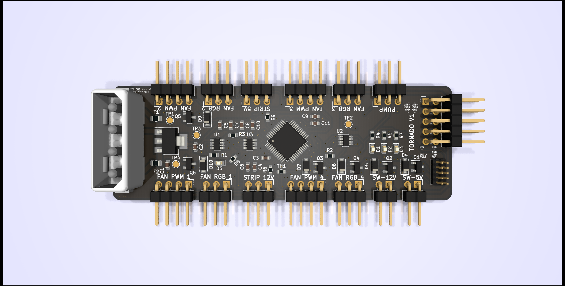
| Qty | Value | Footprint | References |
|---|---|---|---|
| 6 | 2N7002 | Package_TO_SOT_SMD:SOT-23 | Q1, Q2, Q3, Q4, Q5, Q6 |
| 6 | SM4007PL | Diode_SMD:D_SOD-123F | D4, D5, D7, D8, D9, D10 |
| 5 | 100nF | Capacitor_SMD:C_0603_1608Metric | C3, C5, C7, C8, C9 |
| 5 | 10K | Resistor_SMD:R_0603_1608Metric | R1, R2, R3, R6, R9 |
| 4 | CONN_FAN | Connector_PinHeader_2.54mm:PinHeader_1x04_P2.54mm_Horizontal | J9, J11, J14, J15 |
| 4 | RED L | LED_SMD:LED_0603_1608Metric | D1, D2, D3, D6 |
| 4 | RGB_FAN_1 | Connector_PinHeader_2.54mm:PinHeader_1x03_P2.54mm_Horizontal | J10, J12, J13, J16 |
| 4 | TestPoint | TestPoint:TestPoint_Pad_D1.5mm | TP1, TP2, TP3, TP4 |
| 3 | RS0102YH8 | Package_TO_SOT_SMD:SOT-23-8 | U1, U2, U3 |
| 2 | 220 | Resistor_SMD:R_0603_1608Metric | R7, R8 |
| 2 | 4.7uF | Capacitor_SMD:C_0603_1608Metric | C10, C11 |
| 2 | Fuse_Small | Fuse:Fuse_0805_2012Metric | F1, F2 |
| 2 | GEN_SWITCH_5V | Connector_PinHeader_2.54mm:PinHeader_1x02_P2.54mm_Horizontal | J7, J8 |
| 1 | 1.5K | Resistor_SMD:R_0603_1608Metric | R4 |
| 1 | 10nF | Capacitor_SMD:C_0603_1608Metric | C6 |
| 1 | 10uF | Capacitor_SMD:C_0603_1608Metric | C1 |
| 1 | 1uF | Capacitor_SMD:C_0603_1608Metric | C4 |
| 1 | 22uF | Capacitor_SMD:C_0603_1608Metric | C2 |
| 1 | 350211-1 | TerminalBlock:TerminalBlock_bornier-4_P5.08mm | J5 |
| 1 | 470 | Resistor_SMD:R_0603_1608Metric | R5 |
| 1 | AMS1117-3.3 | Package_TO_SOT_SMD:SOT-223-3_TabPin2 | U4 |
| 1 | BOARD_TEMP | Resistor_SMD:R_0603_1608Metric | TH1 |
| 1 | LED_STRIP_12V | Connector_PinHeader_2.54mm:PinHeader_1x03_P2.54mm_Horizontal | J1 |
| 1 | LED_STRIP_5V | Connector_PinHeader_2.54mm:PinHeader_1x03_P2.54mm_Horizontal | J3 |
| 1 | PUMP | Connector_PinHeader_2.54mm:PinHeader_1x03_P2.54mm_Horizontal | J6 |
| 1 | STM32F072C8Tx | Package_QFP:LQFP-48_7x7mm_P0.5mm | U5 |
| 1 | SWD DEBUGG | Connector_PinHeader_1.27mm:PinHeader_2x05_P1.27mm_Vertical | J2 |
| 1 | USB PIN | Connector_PinHeader_2.54mm:PinHeader_2x05_P2.54mm_Horizontal | J4 |
It measures 86 × 29 mm and has 4 copper layers, 1.66 mm thick.
64 parts, built around the RS0102YH8, AMS1117-3.3 and SM4007PL. The full list of its parts is on this page, with links to each part's symbol and footprint where PCBKit's library has them.
From the stan-one/tornado-pcb repository on GitHub, at the commit this page was made from: the board is fan_control_pcb.kicad_pcb and its schematic fan_control_pcb.kicad_sch. PCBKit opens the board in the browser, with nothing to install.
Its repository publishes it under the MIT licence: you may reuse it on that licence's terms (keep the author's notice, and for a copyleft licence share your changes alike).


Cube-Line/T12_SolderingStation
T12_SolderingStation base on ATMEL328P

zapta/ble_stepper_motor_analyzer
A low cost stepper motor analyzer that uses wireless BLE link to display the data in real time on a Windows/Mac/Linux PC.

bitfieldaudio/otto-hardware
OTTO hardware files for upcoming beta. WORK IN PROGRESS

ut-ras/chessbot
Python/MQTT software, Raspberry Pi Config files, PCB Schematics for an autonomous chess playing robot

cjheath/jlcbasic
JLC Basic parts library for Kicad fetched and converted from EasyEDA
