2 layers57.3 × 19 mm

 Stalis/MX-Cherry-4x2-array-with-LED
Stackable PCB module of MX Cherry switches with 1U Keycaps using button matrix with diode topology and LED matrix
MX Cherry 4x2 is an open-source printed circuit board by Stalis, from the Stalis/MX-Cherry-4x2-array-with-LED repository on GitHub. It is a 2-layer board of 78.7 × 38.1 mm with 26 parts on 36 nets, routed with 361 tracks and 34 vias.
Its parts include 8 diodes, 8 switches and 2 connectors. It belongs with the lEDs and displays boards of this library.
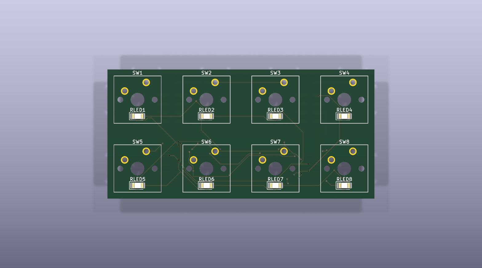
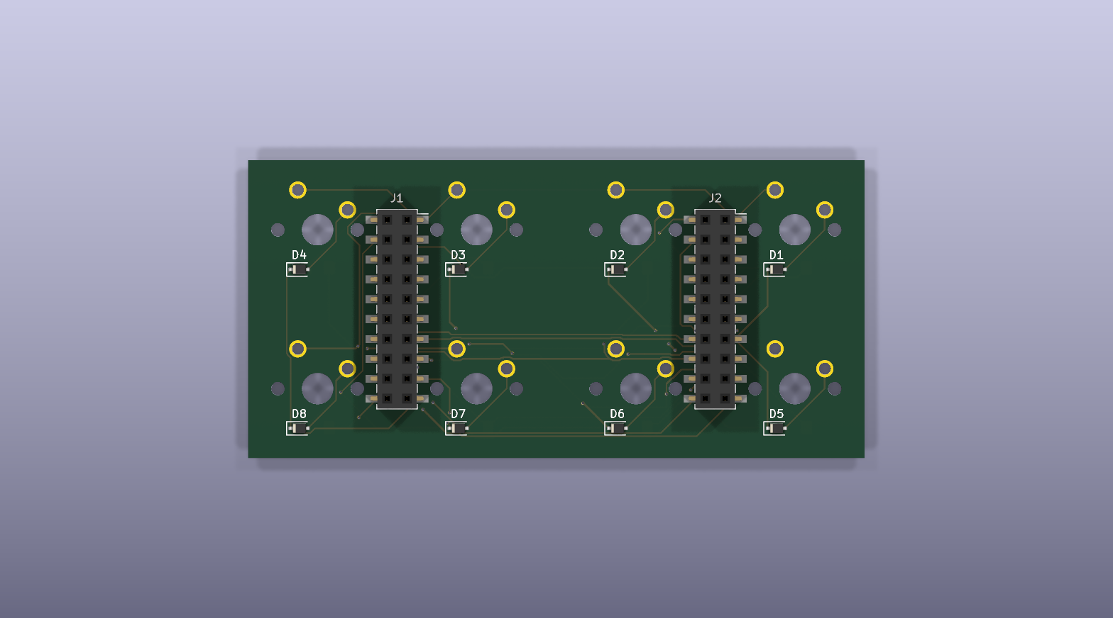
Compact 8-key Cherry MX keyboard module: 4 columns x 2 rows. It has no onboard microcontroller and is intended for connection to an external controller or breadboard.
J1 and J2: 2x10, 2.54 mm pitch, on the bottom side of the board.Key layout:
COL_0 | COL_1 | COL_2 | COL_3 | |
|---|---|---|---|---|
ROW_0 | SW1 / D1 / RLED1 | SW2 / D2 / RLED2 | SW3 / D3 / RLED3 | SW4 / D4 / RLED4 |
ROW_1 | SW5 / D5 / RLED5 | SW6 / D6 / RLED6 | SW7 / D7 / RLED7 | SW8 / D8 / RLED8 |
Each key has a series diode, D1 through D8, to prevent ghosting during matrix scanning. LEDs RLED1 through RLED8 form an independent matrix with the same four columns and two rows.
J1 and J2 are electrically identical: use either connector, or both to mount the module. Pin numbering follows the standard 2x10 connector convention: odd pins are on one row and even pins on the other.
| Pin | Signal | Function |
|---|---|---|
| 1 | SW_0_ROW_0 | switch-matrix row 0 |
| 2 | LED_0_ROW_0 | LED-matrix row 0 |
| 3 | SW_0_ROW_1 | switch-matrix row 1 |
| 4 | LED_0_ROW_1 | LED-matrix row 1 |
| 5-12 | NC | not connected |
| 13 | SW_0_COL_0 | switch-matrix column 0 |
| 14 | LED_0_COL_0 | LED-matrix column 0 |
| 15 | SW_0_COL_1 | switch-matrix column 1 |
| 16 | LED_0_COL_1 | LED-matrix column 1 |
| 17 | SW_0_COL_2 | switch-matrix column 2 |
| 18 | LED_0_COL_2 | LED-matrix column 2 |
| 19 | SW_0_COL_3 | switch-matrix column 3 |
| 20 | LED_0_COL_3 | LED-matrix column 3 |
The controller must scan both matrices externally. The PCB has no LED current-limiting resistors; use an external current-limiting circuit or LED driver.
| Quantity | References | Footprint |
|---|---|---|
| 8 | SW1-SW8 | Cherry MX 1U, PCB mount |
| 8 | D1-D8 | SOD-323F |
| 8 | RLED1-RLED8 | LED 1206, 3216 Metric |
| 2 | J1, J2 | SMD socket 2x10, 2.54 mm |
The schematic does not specify diode ratings or LED color and electrical parameters. Select them for the voltage and current of the external driver.
The following DRC findings are expected for this layout and should be excluded individually with a comment in KiCad after mechanical clearance is confirmed. Do not disable these checks globally.
| DRC check | Count | Rationale |
|---|---|---|
npth_inside_courtyard | 8 | The Cherry MX locating holes are through-holes, while J1 and J2 are bottom-side SMD connectors. The overlaps are courtyard-only; verify the connector body and pads clear the switch locating pins. |
courtyards_overlap | 8 | Each top-side LED is intentionally placed at its associated switch for backlighting. |
footprint_symbol_field_mismatch | 8 warnings | Diodes D1-D8 have a schematic-only Sim.Device field that is absent from their footprints. This does not affect fabrication or electrical connectivity. |
MX Cherry 4x2.kicad_pro - KiCad project.MX Cherry 4x2.kicad_sch - main schematic.MX Cherry 4x2.kicad_pcb - PCB layout.switch_module.kicad_sch and led_module.kicad_sch - reusable sheets for one switch with a diode and one LED.jlcpcb/ and production/ - previously exported manufacturing files.The BOM and CPL files in
jlcpcb/andproduction/are outdated relative to the current schematic and PCB. They omitRLED1throughRLED8and describe the connectors as 1x10. Re-export Gerbers, BOM, and CPL from the current project before ordering.
The project was created with KiCad 10. Open MX Cherry 4x2.kicad_pro in KiCad, or check it from the command line:
/Applications/KiCad/KiCad.app/Contents/MacOS/kicad-cli sch erc "MX Cherry 4x2.kicad_sch"
/Applications/KiCad/KiCad.app/Contents/MacOS/kicad-cli pcb drc --schematic-parity "MX Cherry 4x2.kicad_pcb"| Qty | Value | Footprint | References |
|---|---|---|---|
| 8 | D | Diode_SMD:D_SOD-323F | D1, D2, D3, D4, D5, D6, D7, D8 |
| 8 | LED | LED_SMD:LED_1206_3216Metric_Pad1.42x1.75mm_HandSolder | RLED1, RLED2, RLED3, RLED4, RLED5, RLED6, RLED7, RLED8 |
| 8 | SW_Push | Button_Switch_Keyboard:SW_Cherry_MX_1.00u_PCB | SW1, SW2, SW3, SW4, SW5, SW6, SW7, SW8 |
| 2 | Conn_02x10_Odd_Even | Connector_PinSocket_2.54mm:PinSocket_2x10_P2.54mm_Vertical_SMD | J1, J2 |
It measures 78.7 × 38.1 mm and has 2 copper layers, 1.6 mm thick.
26 parts. The full list of its parts is on this page, with links to each part's symbol and footprint where PCBKit's library has them.
From the Stalis/MX-Cherry-4x2-array-with-LED repository on GitHub, at the commit this page was made from: the board is MX Cherry 4x2.kicad_pcb and its schematic MX Cherry 4x2.kicad_sch. PCBKit opens the board in the browser, with nothing to install.
Its repository states no licence, so its author keeps all rights: ask Stalis before reusing the design.

hackclub/OnBoard
💡 Join 1,000 teenagers and make your first PCB with a $100 grant!


harbaum/galagino
A Galaga, Pac-Man and Donkey Kong arcade emulator for the ESP32

Luos-io/luos_engine
Open-source and real-time orchestrator for cyber-physical-systems, to easily design, test and deploy embedded applications and digital twins.

google/walt
A device for measuring latency of physical sensors and outputs on phones and computers
