
2 layers63.5 × 63.5 mm
Main pcb
peterkrull/quad
Firmware, hardware and documentation for my autonomous quad copter project
45 parts210GPL-3.0
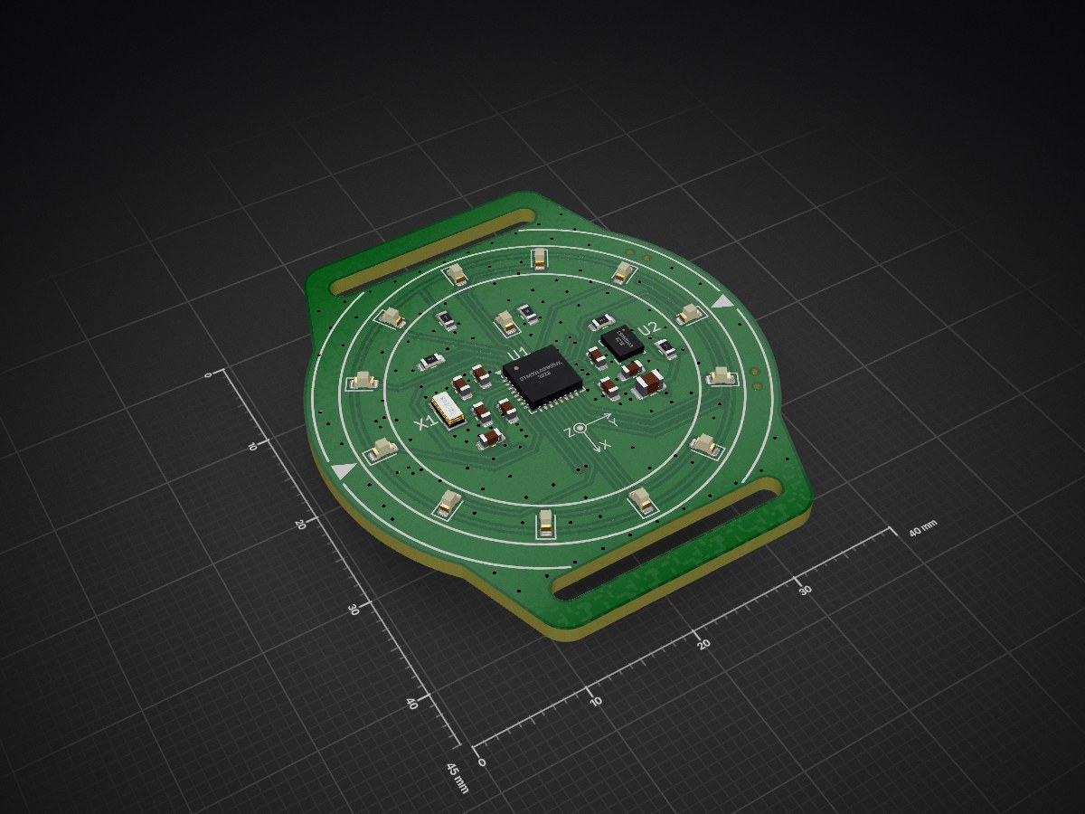
 Stachu1/STM32_Watch
A minimalist, bare-metal wristwatch built around an STM32L0 microcontroller. No HAL, no RTOS, no libraries. Just registers.
STM32 Watch is an open-source printed circuit board by Stachu1, from the Stachu1/STM32_Watch repository on GitHub. It is a 2-layer board of 40 × 45 mm with 45 parts on 35 nets, routed with 214 tracks and 153 vias.
It is built around the LSM6DS3. Its parts include 13 diodes, 11 capacitors, 5 resistors, 2 ICs and 2 switches. It belongs with the wearables boards and the STM32 boards of this library.
A minimalist, bare-metal wristwatch built around an STM32L0 microcontroller. No HAL, no RTOS, no libraries. Just registers.
This is a fully custom PCB watch powered by a CR2032 coin cell, using 12 discrete LEDs arranged like a traditional analog dial. Time is displayed using LED “hands”, with additional modes for voltage, temperature, time setting, and a physics-based pendulum simulation.
Battery voltage = Hour / 10 + 2V
(If hour hand is at 9 the battery voltage is 0.9V + 2V = 2.9V)
IMU/MCU temperature = Hour * 5°C + Minute * 0.1°C
(If hour hand is at 4 and minute hand is at 35 the temperature is 4 * 5°C + 35 * 0.1°C = 23.5°C)
Hour hand running in a circle indicated you are in the time setting mode. Press Upper button to go into hour setting then press lower button to move the hour hand form 12 to 1, 2, 3 up to the current time. Confirm with the Upper button. Reapeat for minutes. After confirming minutes the watch will go back to Time display mode.
If the LEDs at 3 and 9 blink the IMU is disabled. You can enable it by pressing both buttons at once. This will enable the IMU and change mode to Time display.
IF the IMU is enbaled ther hour hand will behave like a pendulum with very low friction. I reacts to the acceleration vector in the XY plane so either tilting or moving the watch arround can cause the hour hand to move.
By double tapping the watch you can add 5 rotations a seconds to the pendulum in the current rotation direction.
If you wanna disalbe the IMU just press both buttons at once. The watch will disable the IMU and go back to the Time display mode.
| Current Mode | Action | Effect |
|---|---|---|
| Time display | Upper button | Change brightness |
| Time display | Double tap | Change brightness (if IMU enabled) |
| Time display | Lower button | Change mode to Stats (battery voltage) |
| Statistics | Upper button | Cycle stats (voltage/temperature) |
| Statistics | Lower button | Change mode to Time setting |
| Time setting | Upper button | Set hour/minute or confirm and change mode to Time display |
| Time setting | Lower button | Change mode to Pendulum simulation or increment hour/minute hand |
| Pendulum simulation | Upper button | Change brightness |
| Pendulum simulation | Double tap | Add +/- 5 rotations/second to the pendulum speed |
| Pendulum simulation | Upper & Lower buttons | Enable/Disable IMU (All the IMU features won't work if the IMU is disabled) |
| Pendulum simulation | Lower button | Change mode to Time display |
Tested on a CR2032 @ ~2.9V
| Mode | Current | Wakeup |
|---|---|---|
| Active (display on) | ~3mA | - |
| Stop mode (sleep) | 22uA | AWT or Buttons |
| Ultra low power (IMU off) | 5.5uA | Buttons |
| Stop mode, no IMU mounted | 2.3uA | Buttons |
All LEDs are connected to ground through a single 100 Ω resistor, which is acceptable because only one LED is on at a time.
The RST pin has a single 100 nF capacitor, as there is an internal pull-up (~40 kΩ).
The I2C lines have external 10 kΩ pull-ups, but it would likely be possible to use weaker internal pull-ups if the frequency were reduced (not tested).
On the back side of the PCB, there are test points for SWD programming and UART debugging.
This project is intentionally low-level:
LEDs are updated in the IRQ handler, which runs every 100 µs. If a hand is to be shown, the LED is turned on at the beginning of its time slot and turned off when local_step reaches the hand’s brightness or at the end of the time slot. This approach ensures that only one LED is on at a time, limiting peak current and reducing battery voltage drop.
The STM32’s RTC runs on the low-speed external oscillator, and the time can be set by the user. Due to the high ESR of the crystal, the LSE drive strength had to be set to medium-high (LSEDRV in RCC_CSR).
The two interrupt pins on the LSM6DSM are used to detect double tap and absolute wrist tilt. Double tap is only available when the watch is awake, as it requires a significantly higher sampling rate.
Battery voltage is measured by reading the internal voltage reference and calculating the supply voltage. This works well, but due to the high internal resistance of the battery, the measured value is about 100 mV lower than the actual open-circuit voltage.
Temperature is measured using the IMU if it is enabled, or the internal temperature sensor of the MCU otherwise.
Ambient light sensing is not currently used, but it can be implemented by setting the pin connected to a reverse-biased LED high and then switching it to high-impedance input. The brighter it is, the faster the pin returns to a low state. Unfortunately, in very dark conditions this can take hundreds of milliseconds, which is why it is not used.
This project uses a minimal build setup based on build.c and a nobuild-style workflow:
https://github.com/tsoding/nob.h
cd firmware
clang build.c -o build
./build buildSolder ST-LINK SWD connections to the test points on the back. (Or just hold a pinheader on them)
./build flashYou can also flash the firmware using STM32CubeProgrammer.
text    data     bss     dec     hex filename
10304 56 4160 14520 38b8 firmware.elf| Qty | Value | Footprint | References |
|---|---|---|---|
| 13 | LED | LED_SMD:LED_0603_1608Metric | D1, D2, D3, D4, D5, D6, D7, D8, D9, D10, D11, D12, D13 |
| 8 | TestPoint_Small | TestPoint:TestPoint_Pad_D1.5mm | TP1, TP2, TP3, TP4, TP5, TP6, TP7, TP8 |
| 6 | 100n | Capacitor_SMD:C_0603_1608Metric | C1, C4, C5, C6, C10, C11 |
| 3 | 10k | Resistor_SMD:R_0603_1608Metric | R1, R3, R4 |
| 2 | 100u | Capacitor_SMD:C_1206_3216Metric | C8, C9 |
| 2 | 18p | Capacitor_SMD:C_0603_1608Metric | C2, C3 |
| 2 | MountingHole | STM32_Watch:StrapsConnection_20mm | H1, H2 |
| 2 | SW_Push | STM32_Watch:SHOU_HAN_TS24CA | SW1, SW2 |
| 1 | 100 | Resistor_SMD:R_0603_1608Metric | R2 |
| 1 | 10u | Capacitor_SMD:C_0805_2012Metric | C7 |
| 1 | 1M | Resistor_SMD:R_0603_1608Metric | R5 |
| 1 | 32.768k | Crystal:Crystal_SMD_3215-2Pin_3.2x1.5mm | X1 |
| 1 | Battery_Cell | Battery:BatteryHolder_Renata_SMTU2032-LF_1x2032 | BT1 |
| 1 | LSM6DS3 | Package_LGA:LGA-14_3x2.5mm_P0.5mm_LayoutBorder3x4y | U2 |
| 1 | STM32L031K6Ux | Package_DFN_QFN:QFN-32-1EP_5x5mm_P0.5mm_EP3.1x3.1mm_ThermalVias | U1 |
peterkrull/quad
Firmware, hardware and documentation for my autonomous quad copter project

neuroidss/FreeEEG32-beta
as FreeEEG32 plus alpha1.5 test passed, FreeEEG32 project changed to beta version

aeonSolutions/AeonLabs-AI-Volvo-MKII-Open-Hardware
Volvo MKII Open Hardware


neuroidss/FreeEEG32-alpha1.0
ALPHA1.0 TEST FAILED, USE NEW VERSION INSTEAD FreeEEG32 alpha1.0 32 channels mobile electroencephalography under GNU AGPL 24 bits, 4kSPS ADCs 4x AD7770 MCU STM32F427ZI WIFI ESP-12F (ESP8266) USB CP2102N Accel & hyro…

neuroidss/FreeEEG32-alpha1.5
4xAD7771BCPZ 64 kSPS, ADR4525BRZ 2.5V REF +-0.02%, STM32H743ZIT6 MCU 1027 DMIPS
It measures 40 × 45 mm and has 2 copper layers, 1.6 mm thick.
45 parts, built around the LSM6DS3. The full list of its parts is on this page, with links to each part's symbol and footprint where PCBKit's library has them.
From the Stachu1/STM32_Watch repository on GitHub, at the commit this page was made from: the board is PCB/STM32_Watch.kicad_pcb and its schematic PCB/STM32_Watch.kicad_sch. PCBKit opens the board in the browser, with nothing to install.
Its repository states no licence, so its author keeps all rights: ask Stachu1 before reusing the design.