2 layers64 × 22.9 mm
Console s3
jmcpheron/pico-quorum
Several people, several keys, one Safe. Hardware approvals for Safe multisig wallets.
45 partsMIT

 ssjowowo/bleep
Most universal remotes either have a screen and few buttons, or lots of buttons and no screen. Bleep has both. The touchscreen shows activities, now-playing and smart-home controls.
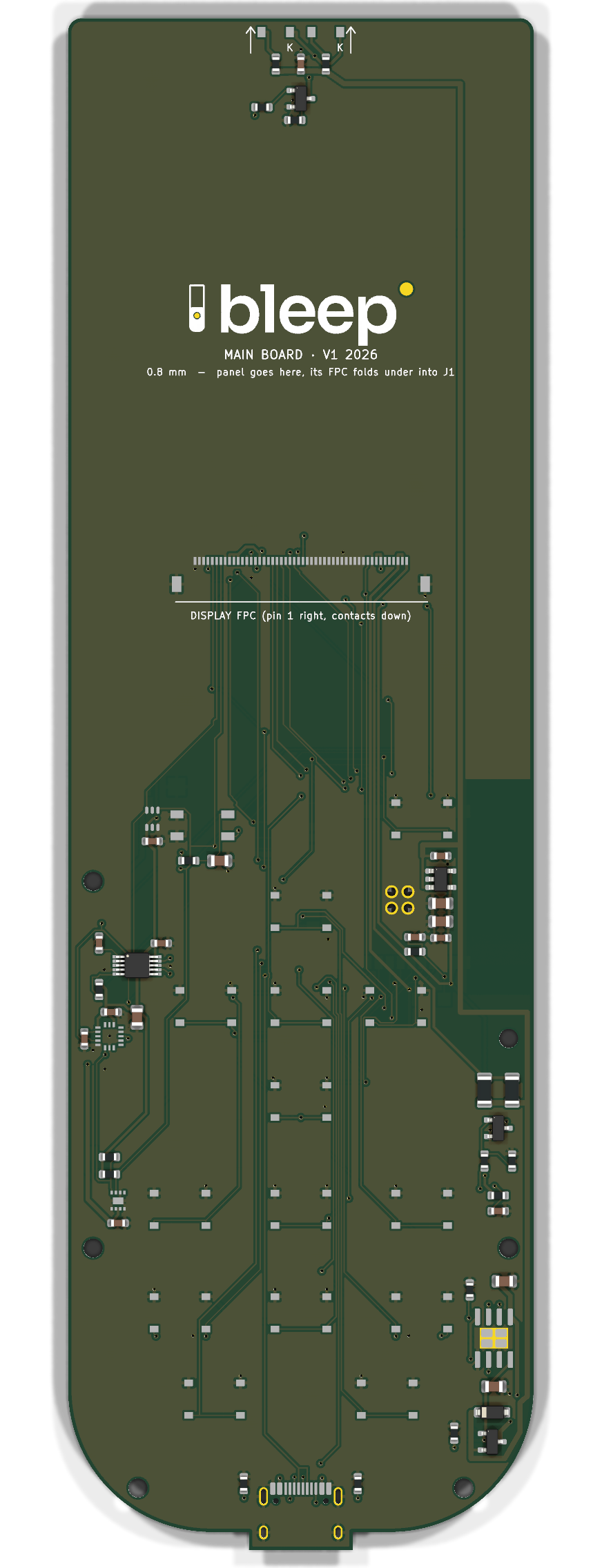
Mainboard placed is an open-source printed circuit board by ssjowowo, from the ssjowowo/bleep repository on GitHub. It is a 2-layer board of 53.9 × 177.5 mm with 80 parts on 59 nets.
It is built around the ESP32-S3-WROOM-1-N8R2, LTR-303ALS-01 and IRM-H638T/TR2, with the MAX17048G+T10, ME6211C33M5G-N and MMA8452QR1 among its other parts. Its parts include 18 resistors, 17 capacitors, 14 switches, 8 ICs and 3 diodes. It belongs with the computers and single-board computers boards and the ESP32 boards of this library.


A DIY touchscreen universal remote. It's built around an ESP32-S3 on a main board of our own, with a 3.5″ IPS touch display, 14 physical keys, IR send and learn, haptics, and Home Assistant control over Wi-Fi. The case is 3D-printed and only 13 mm thick.
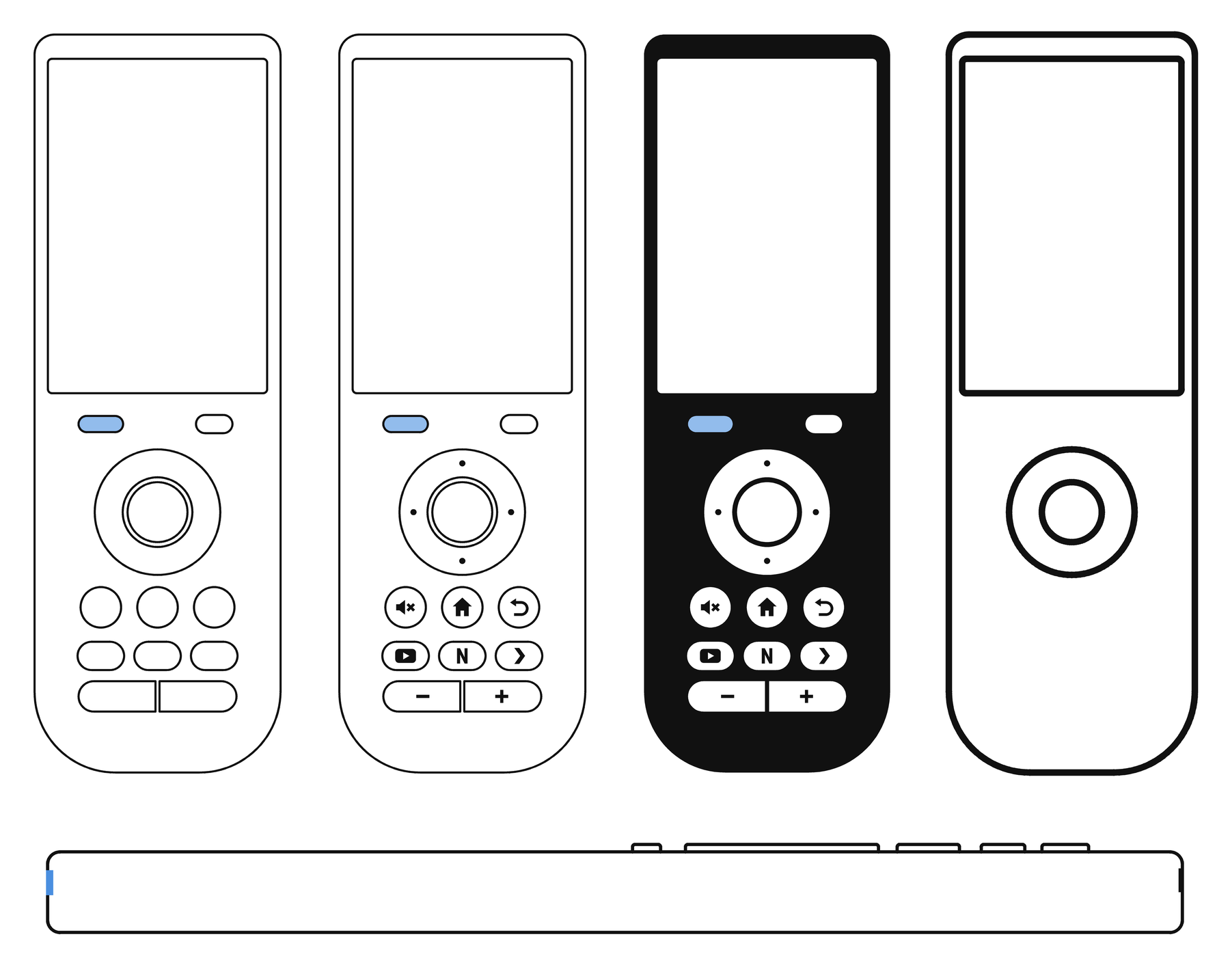
Most universal remotes either have a screen and few buttons, or lots of buttons and no screen. Bleep has both. The touchscreen shows activities, now-playing and smart-home controls. The keys you use without looking stay physical: a D-pad ring with OK, Back, Home, Mute, three app keys (YouTube, Netflix, Plex) and a volume rocker.
The hardware is designed for all of this. The firmware's app and UI run today in an emulator (on the PC or in a browser) while the boards are being made; the ESP32-S3 port comes when they arrive. See firmware/README.md.
The industrial design comes from a concept pack made in Claude Design (design 1b "Pebble", in design/). The brand (wordmark, logo lockup) comes from the Bleep brand book.
| Part | State |
|---|---|
| Main board v1 | Ordered from JLCPCB on 2026-10-08 (5 boards, 2 assembled). The design is locked: the files in hardware/mainboard/ are the ones in production. |
| Enclosure | Ready to print. The back plate is flat, with room for a 4.0 × 50 × 85 mm Li-Po (405085) under the screen. |
| Display | BuyDisplay ER-TFT035IPS-6 + capacitive touch, ordered 2026-10-09. Its cable fold gets checked on the real panel before assembly. |
| Battery | Ordered 2026-10-09 (405085 planned; if the cell differs, set BATT in layout.py and rebuild the back plate). |
| Firmware | App and UI (C + LVGL 9) running in a PC/browser emulator with 32 scripted test scenarios; ESP-IDF port next. firmware/ |
| Size | 60.7 × 182.2 × 13.0 mm |
| MCU | ESP32-S3-WROOM-1-N8R2 (8 MB flash, 2 MB PSRAM), antenna at the right edge beside the D-pad |
| Display | 3.5″ IPS 320 × 480, ILI9488 on an 8-bit parallel bus (much faster than SPI), FT6236 capacitive touch |
| Keys | 14 tactile switches, each on its own wake-capable GPIO |
| IR | 2 × VSMB2948SL LEDs (≈ 125 mA peaks), IRM-H638T receiver for learning |
| Sensors | MMA8452Q accelerometer, LTR-303ALS light sensor, MAX17048 fuel gauge |
| Power | 1-cell Li-Po, TP4056 charger with load sharing, ME6211 3.3 V LDO |
| Board | 2 layers, 0.8 mm, 54 × 178 mm. JLCPCB assembles the top side; you solder the ESP32 module, battery and motor on the underside. |
| Case | PETG, two colours for the key labels (flush inlays), plus translucent blue PETG for the IR and sensor windows (two small separate prints); the board screwed to the front shell (4 × M2×4) and the back plate held by 2 × M2×8 and two snap fingers, all into heat-set inserts |
The parts list, pin map, assembly steps, ordering guide (≈ €130 in total, delivered to Cyprus) and firmware notes are in hardware/README.md.
Everything mechanical comes from one file, hardware/layout.py. It holds the display and part sizes, the key layout, where each part sits, the z stack and the screw points, and it runs fit checks on all of them. Two generators read it:
layout.py writes enclosure/params.scad, and enclosure/remote.scad (OpenSCAD) builds the front shell, its two windows, back plate, key caps and label inlays as STLs, plus interference checks.mainboard/gen_mainboard.py places the parts in KiCad 10 from the same numbers. Freerouting routes it, then the generator adds ground pours, runs DRC and exports Gerbers, BOM and CPL for JLCPCB.The board and the case can't drift apart. Since the board was ordered, layout.py checks every value the board was built from against mainboard/pcb_lock.json. It refuses to run if a case change would move one of them.
design/              concept pack (open the .dc.html files in a browser), brand assets, outline drawings
hardware/
  layout.py          the single source of truth for the mechanics
  build.sh           rebuilds everything from layout.py
  enclosure/         OpenSCAD source and the printable STLs (enclosure/stl/)
  mainboard/         KiCad board, generator, routing logs; fab/ = Gerbers, BOM, CPL (locked)
  viewer/            3D colour viewer (three.js) for trying colourways
  docs/              datasheets and renders
HANDOFF.md current working state, for picking the project up on another machinecd hardware
./build.sh enclosure # STLs, renders and fit checks
./build.sh viewer # meshes for the 3D viewer (viewer/index.html)You need Python 3 (no extra packages) and OpenSCAD 2021.01 or newer, on the PATH or set with OPENSCAD=. The board rebuild (./build.sh pcb) also needs KiCad 10 and Freerouting, and it's disabled while v1 is locked.
To open the 3D viewer locally, run python3 -m http.server -d hardware/viewer 8742 and go to http://localhost:8742.
| Qty | Value | Footprint | References |
|---|---|---|---|
| 14 | TS-1187A-B-A-B | SW_Push_1P1T_XKB_TS-1187A | SW1, SW2, SW3, SW4, SW5, SW6, SW7, SW8, SW9, SW10, SW11, SW12, SW13, SW14 |
| 7 | 1uF | C_0603_1608Metric | C3, C4, C7, C8, C15, C17, C18 |
| 6 | M2 | MountingHole_2.2mm_M2 | H1, H2, H3, H4, H5, H6 |
| 5 | 10uF | C_0805_2012Metric | C5, C11, C12, C14, C16 |
| 4 | 100k | R_0603_1608Metric | R5, R9, R11, R19 |
| 4 | logo LED dot | LOGO_BACK1, LOGO_BACK2, LOGO_FRONT1, LOGO_FRONT2 | |
| 3 | 100nF | C_0603_1608Metric | C2, C9, C13 |
| 2 | 100R | R_0603_1608Metric | R4, R8 |
| 2 | 10k | R_0603_1608Metric | R1, R10 |
| 2 | 22R | R_0603_1608Metric | R2, R3 |
| 2 | 22R | R_1206_3216Metric | R6, R7 |
| 2 | 4.7k | R_0603_1608Metric | R12, R13 |
| 2 | 5.1k | R_0603_1608Metric | R17, R18 |
| 2 | AO3400A | SOT-23 | Q1, Q2 |
| 2 | VSMB2948SL | VSMB2948SL_SideView | D1, D2 |
| 2 | battery lead pad | TestPoint_Pad_2.0x2.0mm | TP1, TP2 |
| 2 | reset pad | TestPoint_Pad_1.5x1.5mm | TP3, TP4 |
| 1 | 10uF | C_0603_1608Metric | C6 |
| 1 | 220R | R_0603_1608Metric | R20 |
| 1 | 22uF | C_0805_2012Metric | C1 |
| 1 | 3.3k | R_0603_1608Metric | R16 |
| 1 | AO3401A | SOT-23 | Q3 |
| 1 | B5819W | D_SOD-123 | D3 |
| 1 | DRV2605LDGST | MSOP-10_3x3mm_P0.5mm | U3 |
| 1 | ESP32-S3-WROOM-1-N8R2 | ESP32-S3-WROOM-1 | U1 |
| 1 | FPC-05F-50PH15 | FPC-05F-50PH15 | J1 |
| 1 | IRM-H638T/TR2 | IRM-H638T | U6 |
| 1 | LRA 0832 (8 mm coin, wired) | LRA_8mm_WirePads | M1 |
| 1 | LTR-303ALS-01 | LTR-303ALS-01 | U7 |
| 1 | MAX17048G+T10 | MAX17048_TDFN-8_2x2mm | U8 |
| 1 | ME6211C33M5G-N | SOT-23-5 | U2 |
| 1 | MMA8452QR1 | MMA8452Q_QFN-16_3x3mm_P0.5mm | U4 |
| 1 | TP4056 | SOIC-8-1EP_3.9x4.9mm_P1.27mm_EP2.41x3.3mm | U5 |
| 1 | TYPE-C 16PIN 2MD(073) | USB_C_Receptacle_HRO_TYPE-C-31-M-12 | J3 |
It measures 53.9 × 177.5 mm and has 2 copper layers, 0.8 mm thick.
80 parts, built around the ESP32-S3-WROOM-1-N8R2, LTR-303ALS-01, IRM-H638T/TR2 and MAX17048G+T10. The full list of its parts is on this page, with links to each part's symbol and footprint where PCBKit's library has them.
From the ssjowowo/bleep repository on GitHub, at the commit this page was made from: the board is hardware/mainboard/mainboard_placed.kicad_pcb. PCBKit opens the board in the browser, with nothing to install.
Its repository states no licence, so its author keeps all rights: ask ssjowowo before reusing the design.
jmcpheron/pico-quorum
Several people, several keys, one Safe. Hardware approvals for Safe multisig wallets.


HeyPCB/whisker
Drop-in controller for Petoi's Nybble robot cat running the stock OpenCat firmware: ATmega328P, PCA9685, MPU-6050, USB-C, 3 A buck, protected battery input. 4-layer KiCad 10 board plus printed cradle.

LastZactionHero/defcon-silent-disco
RP2040-based DEF CON silent disco badge — KiCad project + tooling

mitra42/frugal-iot-hw-sensor
A simple, un-opinionated, multi-purpose sensor board, that can be wired to sensors using most common interfaces (I2C, ModBus, OneWire, Analog) with onboard charging and external antenna.

e-ale/BaconBitsCapeHW
Design files for the Bacon Bits MiniCape for the PocketBeagle