2 layers40.8 × 23.6 mm
 squidgeefish/eMMC-Reader
A GL3224-based eMMC reader
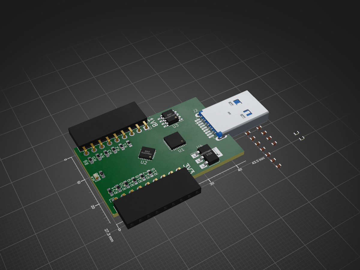
EMMC Reader is an open-source printed circuit board by squidgeefish, from the squidgeefish/eMMC-Reader repository on GitHub. It is a 2-layer board of 43.5 × 27.3 mm with 48 parts on 59 nets.
It is built around the W25X20CLSNIG, LM1117MP-1.8 and TXS02612RTW. Its parts include 28 resistors, 12 capacitors, 4 ICs, 3 connectors and 1 diode.


A GL3224-based eMMC reader
The Sabrent USB readers that had this chip were recently (2022?) updated to use the 48-QFN version with dual LUNs. This happened to break the single-bit eMMC mode, and that makes me very sad. Rather than trawling eBay for NOS packaging, I figured I should just make a better tool.
This also includes a TXS02612 that is being used as a 1.8V level shifter like on an Exploitee.rs Low Voltage eMMC Adapter because those are great.
Note that this is a mux, which isn't necessary in this application. I could wire it up to an SD card socket, but that's overkill. According to TI's Product Overview for SDIO voltage translators, the TXS0206 is a non-mux version of this, but it only supports 60Mbps (as opposed to 120Mbps) and is a WCSP. I've gotten more than 60Mbps out of an exploitee.rs board in single-bit mode, so I'm going to stick with the proven chip.
Because I don't trust you not to break it...
The GL3224 supports USB 3.0 (5Gbps). To implement that with a USB-C connector, there are two options:
SS[R,T]X lines as well as a 5K1 pulldown on CC1. The computer into which this is plugged will have to figure out which pair is live.HD3SS3220 since you can't trust a user to plug the cable in the "right" way.USB-C plugs suck because they need thin PCBs and you will break one off in your computer at some point. Unless you use a (technically illegal) extension cable, and then we're back to the same impasse as we had with the receptacle in the first place. It's easier and more robust to use a USB 3.0 Type-A connector (I typically wind up using the Sabrent USB reader with a USB 2.0 extension cable anyway to keep the clock speeds down).
Note that this schematic is a little more grand than the bare minimum necessary; the Sabrent reader that inspired this project doesn't bother with the external oscillator.
| Qty | Value | Footprint | References |
|---|---|---|---|
| 12 | 0 | Resistor_SMD:R_0603_1608Metric_Pad0.98x0.95mm_HandSolder | R1, R2, R3, R4, R5, R6, R16, R17, R18, R19, R20, R21 |
| 12 | 47 | Resistor_SMD:R_0603_1608Metric_Pad0.98x0.95mm_HandSolder | R7, R8, R9, R10, R11, R12, R22, R23, R24, R25, R26, R27 |
| 5 | 0.1uF | Capacitor_SMD:C_0603_1608Metric_Pad1.08x0.95mm_HandSolder | C3, C6, C7, C8, C12 |
| 2 | 10pF | Capacitor_SMD:C_0603_1608Metric_Pad1.08x0.95mm_HandSolder | C1, C2 |
| 2 | 1uF | Capacitor_SMD:C_0603_1608Metric_Pad1.08x0.95mm_HandSolder | C4, C5 |
| 2 | 4.7uF | Capacitor_SMD:C_0603_1608Metric_Pad1.08x0.95mm_HandSolder | C10, C11 |
| 2 | Conn_01x09_Socket | Connector_PinSocket_2.54mm:PinSocket_1x09_P2.54mm_Horizontal | J1, J3 |
| 1 | 1M | Resistor_SMD:R_0603_1608Metric_Pad0.98x0.95mm_HandSolder | R15 |
| 1 | 2.2uF | Capacitor_SMD:C_0603_1608Metric_Pad1.08x0.95mm_HandSolder | C9 |
| 1 | 220 | Resistor_SMD:R_0603_1608Metric_Pad0.98x0.95mm_HandSolder | R13 |
| 1 | 330 | Resistor_SMD:R_0603_1608Metric_Pad0.98x0.95mm_HandSolder | R28 |
| 1 | 680 | Resistor_SMD:R_0603_1608Metric_Pad0.98x0.95mm_HandSolder | R14 |
| 1 | LED_Small_Filled | LED_SMD:LED_0603_1608Metric | D1 |
| 1 | LM1117MP-1.8 | Package_TO_SOT_SMD:SOT-223-3_TabPin2 | U4 |
| 1 | TXS02612 | Package_DFN_QFN:QFN-24-1EP_4x4mm_P0.5mm_EP2.15x2.15mm_ThermalVias | U2 |
| 1 | USB3_A | Connector_USB:USB3_A_Plug_Wuerth_692112030100_Horizontal | J2 |
| 1 | W25X20CLSN | Package_SO:SOIC-8_3.9x4.9mm_P1.27mm | U3 |
| 1 | ~ | Package_DFN_QFN:QFN-32-1EP_5x5mm_P0.5mm_EP3.1x3.1mm_ThermalVias | U1 |
It measures 43.5 × 27.3 mm and has 2 copper layers, 1.6 mm thick.
48 parts, built around the W25X20CLSNIG, LM1117MP-1.8 and TXS02612RTW. The full list of its parts is on this page, with links to each part's symbol and footprint where PCBKit's library has them.
From the squidgeefish/eMMC-Reader repository on GitHub, at the commit this page was made from: the board is hardware/eMMC-Reader.kicad_pcb and its schematic hardware/eMMC-Reader-Lite/eMMC-Reader-Lite.kicad_sch. PCBKit opens the board in the browser, with nothing to install.
Its repository states no licence, so its author keeps all rights: ask squidgeefish before reusing the design.


oscimp/wr_acorn
White Rabbit time and frequency transfer on the Artix7 of the Acorn CLE125

PavitpalSingh2004/TRUESENSE_V2
TrueSense V2 is a compact high-speed reflection spectrometer using the Hamamatsu C12880MA, ESP32-S3, custom PCBs, high-speed ADC acquisition, FT2232H USB, Wi-Fi/UDP streaming, and a PyQt6 GUI for real-time spectrum…

Masaharu41/Midi-Bass-Guitar
A repository for all design work, assembly, and schematics for a robotic bass guitar programmed with MIDI

CatspersCoffee/S100-Boards
S-100 bus boards designed and built: Z80 and 80386 CPU cards, SRAM/DRAM memory, CPLD/FPGA I/O and SPI boards, an 18-slot backplane and bus terminator.
