2 layers94 × 82 mm
 spstack/lightlink-remote-outlet
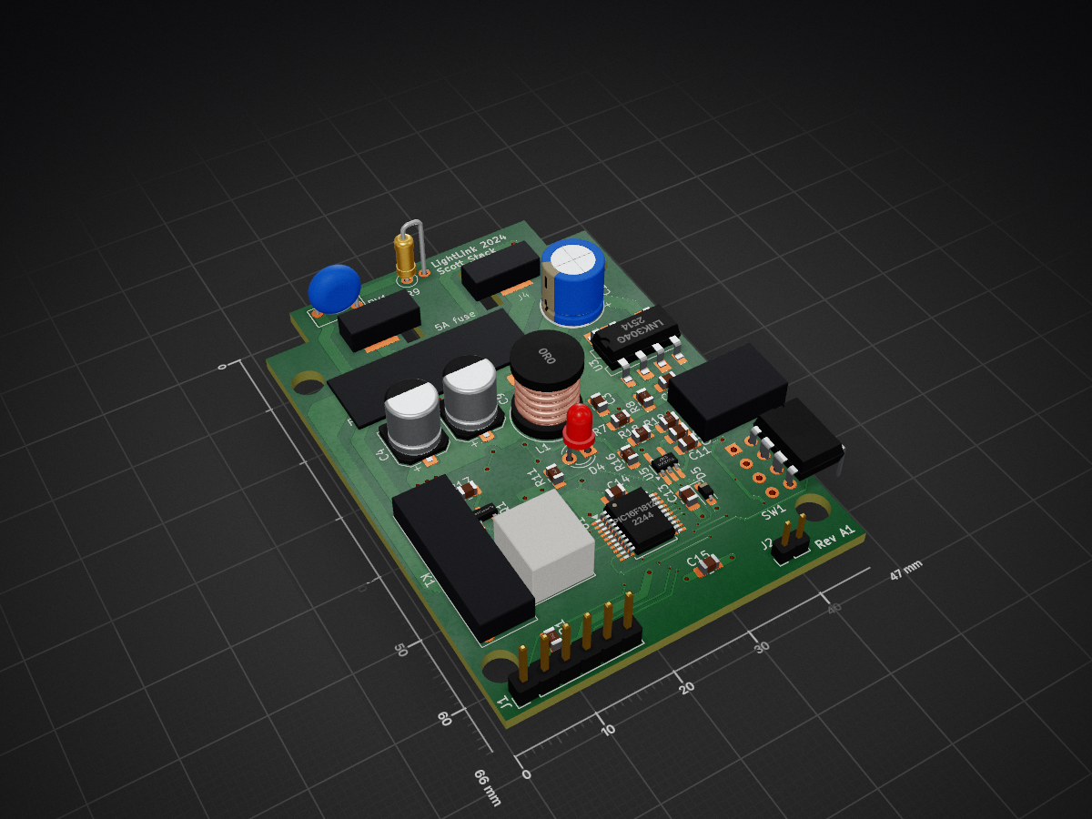
Code and PCB designs for a device that can link a switched power outlet to any other outlet remotely.
Lightlink is an open-source printed circuit board by spstack, from the spstack/lightlink-remote-outlet repository on GitHub. It is a 2-layer board of 80 × 66 mm with 59 parts on 50 nets, routed with 376 tracks and 64 vias.
It is built around the PIC16F18126-I/ST, TPS56339DDC and LNK304GN, with the ES1J-LTP among its other parts. Its parts include 18 resistors, 17 capacitors, 6 diodes, 5 ICs and 5 connectors. It belongs with the PIC boards of this library.


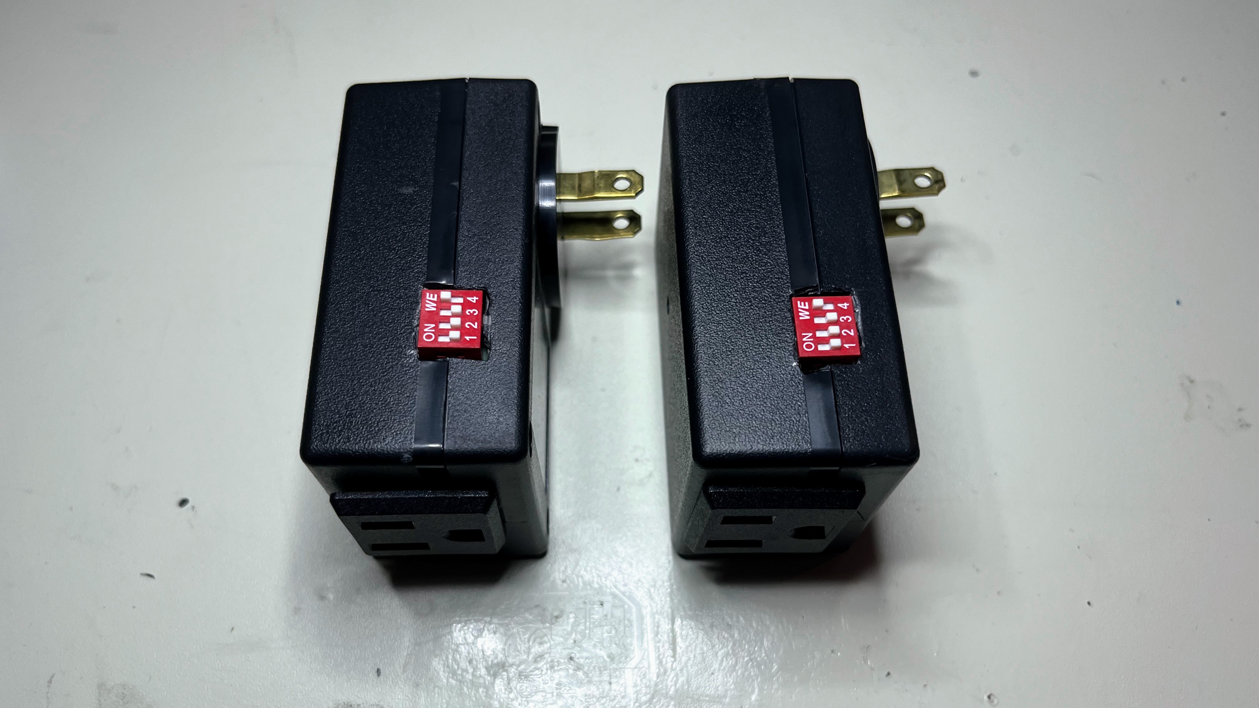
A way to remotely link power outlets! This is an idea taken from the "Switcheroo" device that allows taking an existing switched power outlet and linking it wirelessly with another outlet.
Basically, you can change the location of an outlet that is already hooked up to a switch. The device uses a simple 915MHz wireless transceiver so there's no wifi/bluetooth involved. You just select the channel you want to control and if any device on that channel is powered on or off, all of the devices on that channel will follow it.
It's really useful for me in an apartment where you can't change the wiring (or just don't want to). I made about 10 of these devices to use in multiple locations where there's a switched outlet.
 | 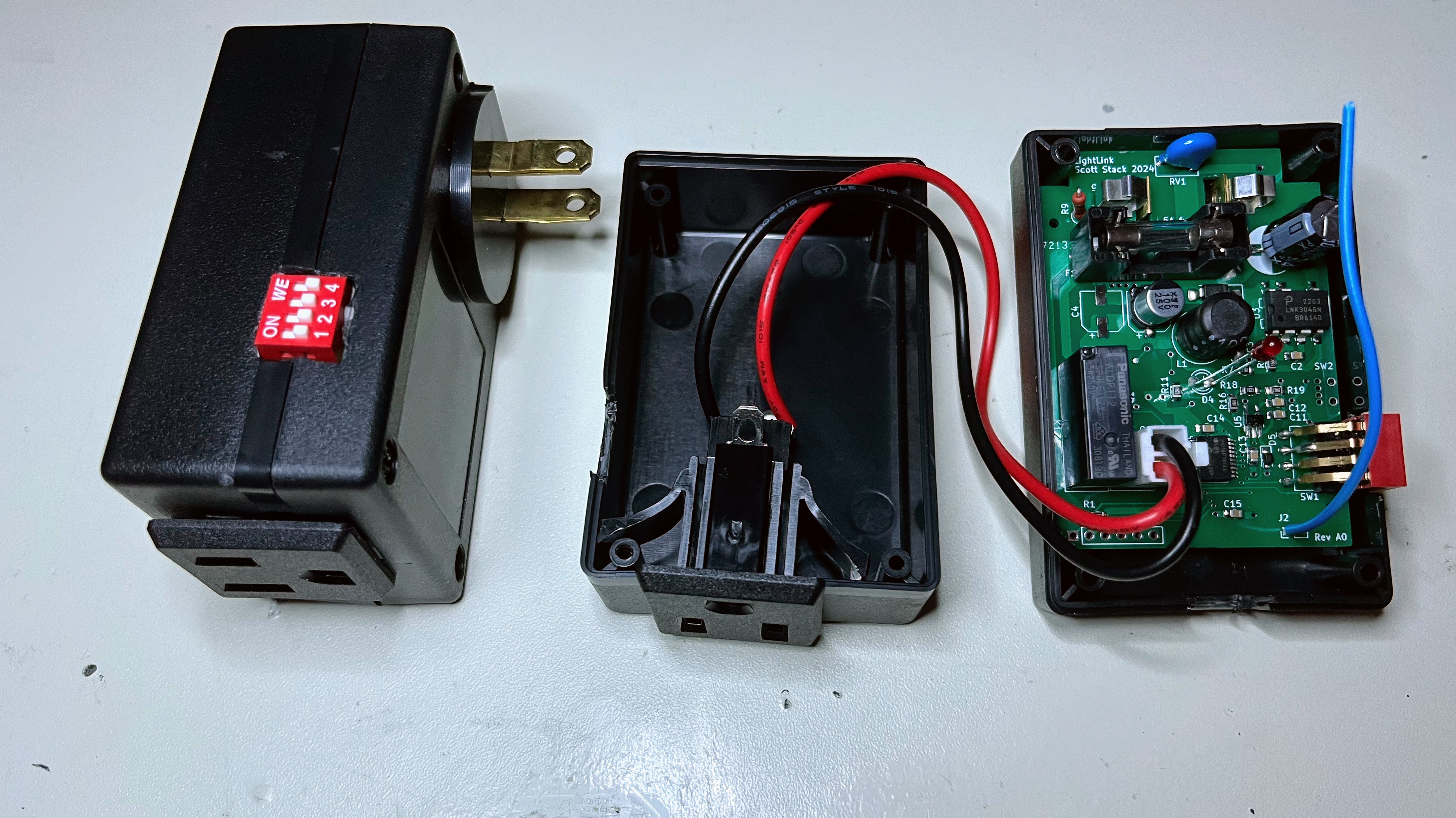 |
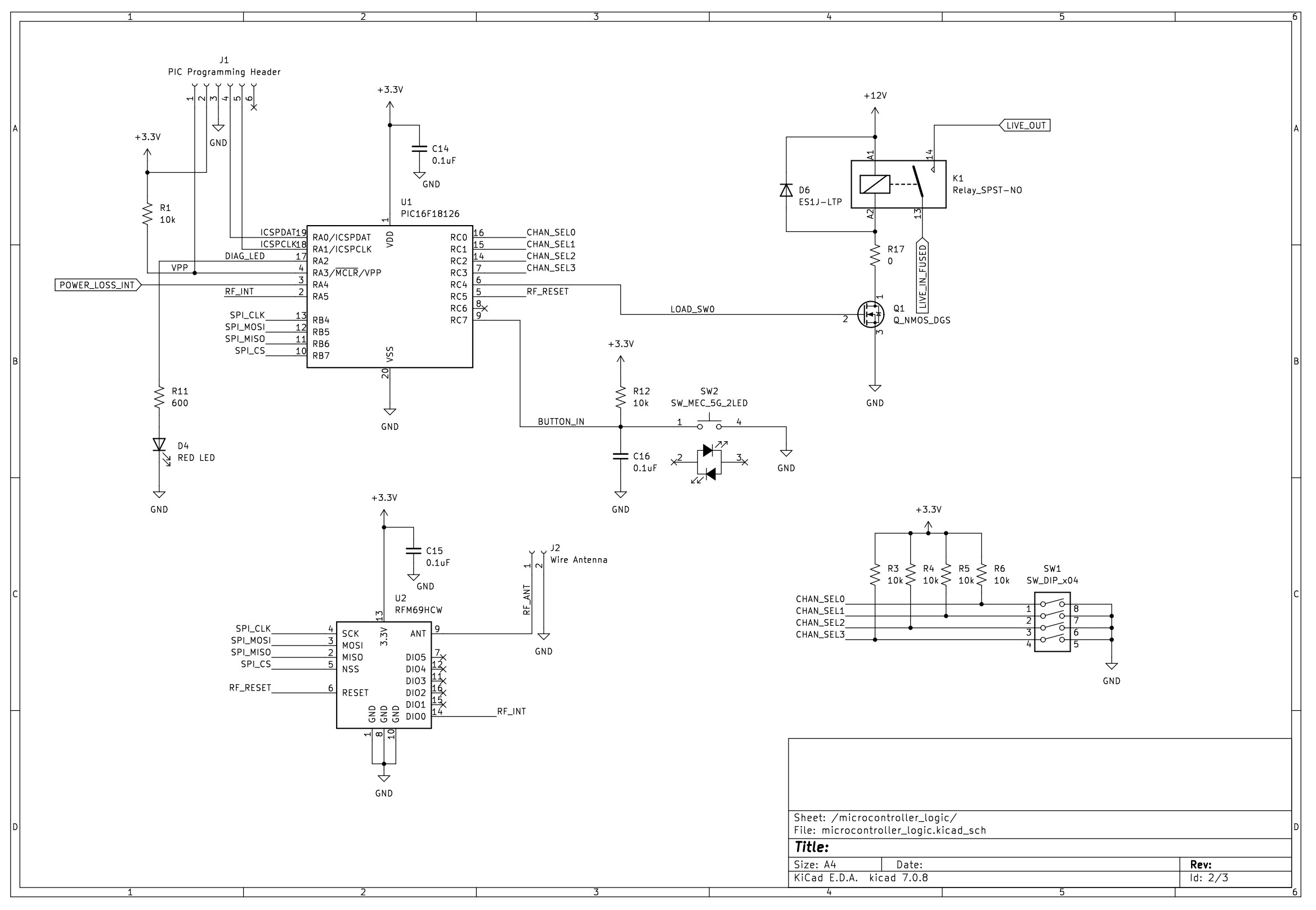
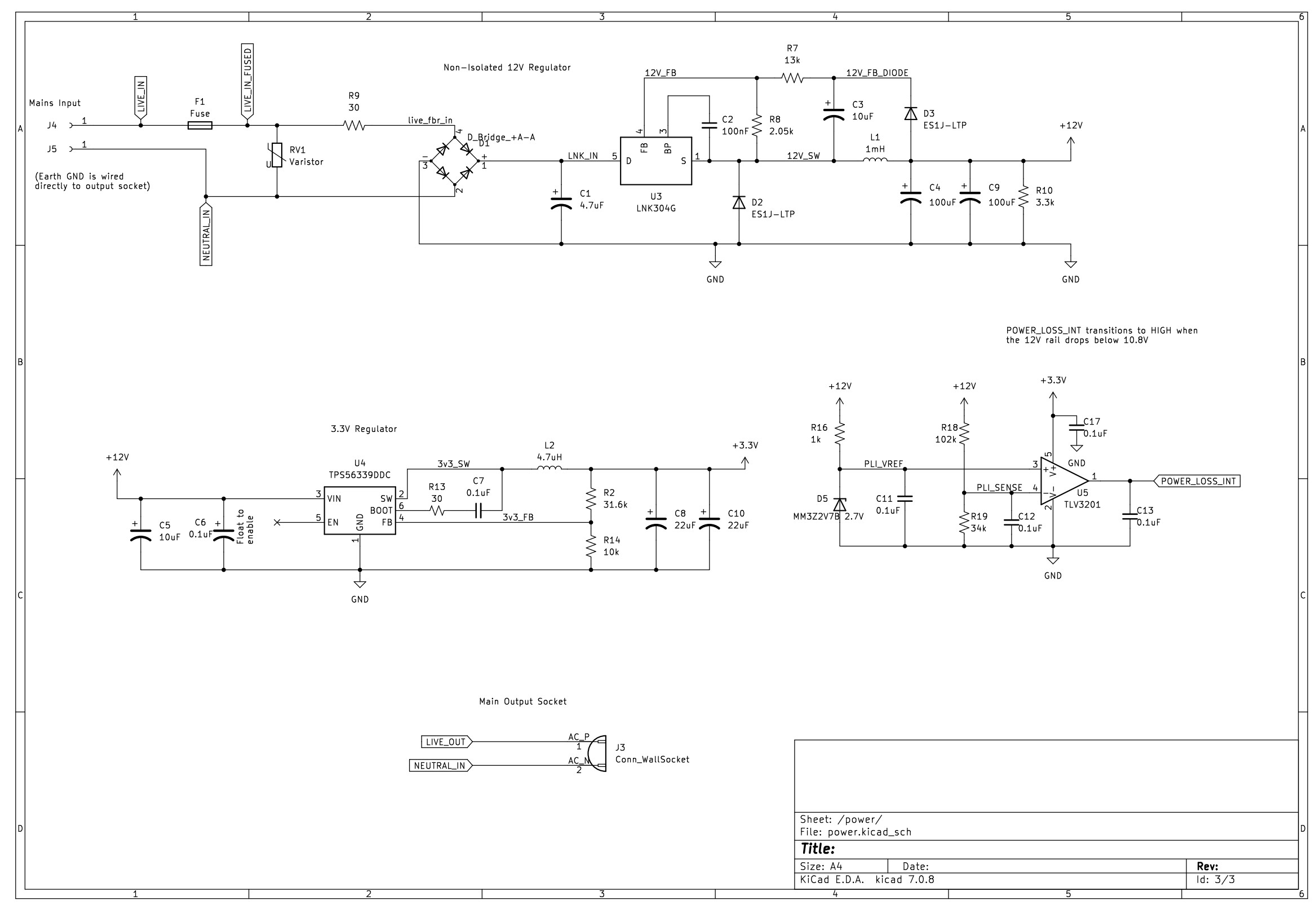
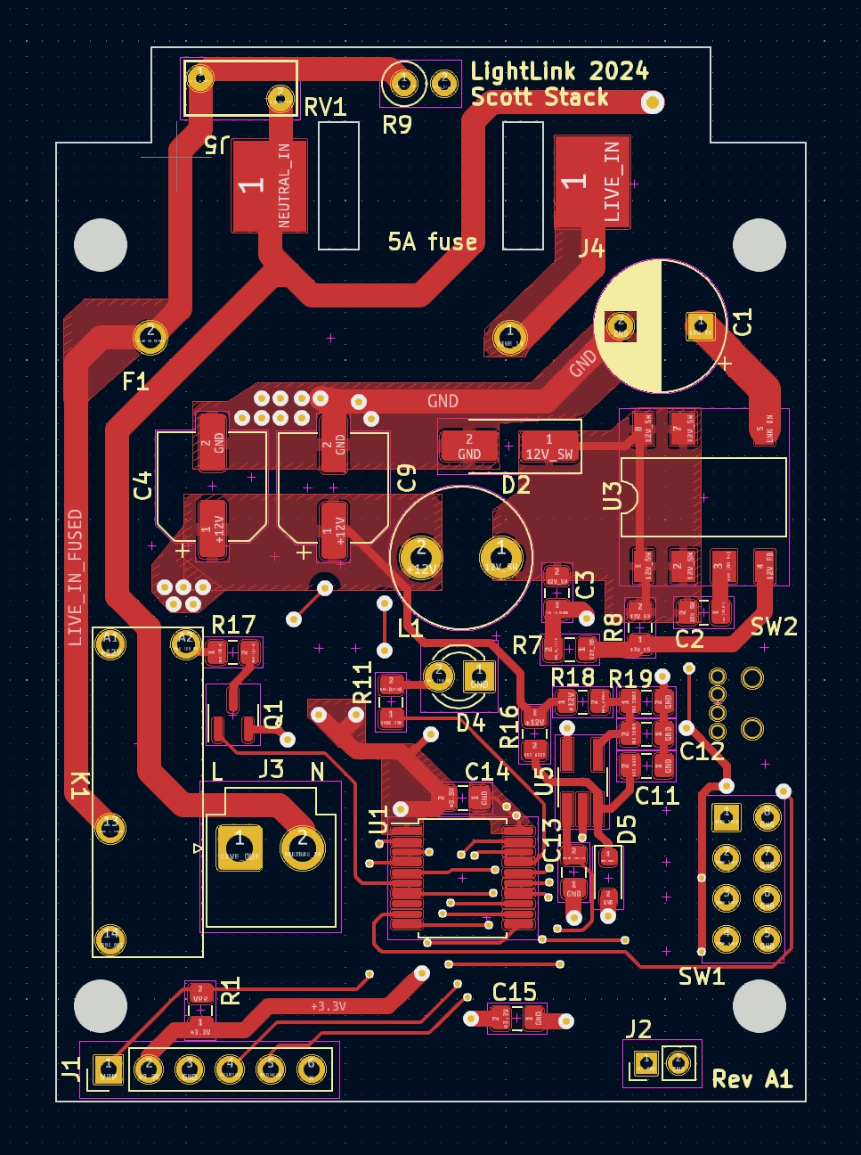
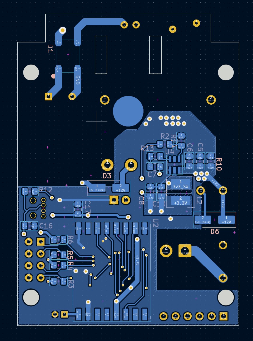
The board was designed in KiCAD and manufactured by JLC PCB. The main components are a PIC microcontroller connected to an RFM69HCW wireless transciever. There's also a relay connected to the live end of the incoming mains voltage and a small set of DIP switches for selecting which channel to transmit on.
The power system is somewhat interesting. A 12V rail is generated through a simple switching regulator that's designed to replace capacitive dropper circuits (small amount of current). This rail contains some very large electrolytic capacitors that serve to store energy and power the rest of the system for a small amount of time when mains voltage is lost. This 12V rail feeds into a second DC-DC switching regulator that powers the digital electronics. If the 12V rail drops below a threshold, a signal is sent to the PIC to transmit the "power down" command to all other LightLinks on it's channel.
| Schematic Sheet 1 | Schematic Sheet 2 |
|---|---|
 |  |
| Board Layout Front | Board Layout Back |
|---|---|
 |  |
| Qty | Value | Footprint | References |
|---|---|---|---|
| 9 | 0.1uF | Capacitor_SMD:C_0805_2012Metric_Pad1.18x1.45mm_HandSolder | C6, C7, C11, C12, C13, C14, C15, C16, C17 |
| 7 | 10k | Capacitor_SMD:C_0805_2012Metric_Pad1.18x1.45mm_HandSolder | R1, R3, R4, R5, R6, R12, R14 |
| 3 | ES1J-LTP | Diode_SMD:D_SMA_Handsoldering | D2, D3, D6 |
| 2 | 100uF | Capacitor_SMD:CP_Elec_6.3x7.7 | C4, C9 |
| 2 | 10uF | Capacitor_SMD:C_0805_2012Metric_Pad1.18x1.45mm_HandSolder | C3, C5 |
| 2 | 22uF | Capacitor_SMD:C_0805_2012Metric_Pad1.18x1.45mm_HandSolder | C8, C10 |
| 2 | Conn_01x01_Socket | connectors_sps:conn_harwin_S1941-46R | J4, J5 |
| 1 | 0 | Capacitor_SMD:C_0805_2012Metric_Pad1.18x1.45mm_HandSolder | R17 |
| 1 | 100nF | Capacitor_SMD:C_0805_2012Metric_Pad1.18x1.45mm_HandSolder | C2 |
| 1 | 102k | Capacitor_SMD:C_0805_2012Metric_Pad1.18x1.45mm_HandSolder | R18 |
| 1 | 13k | Capacitor_SMD:C_0805_2012Metric_Pad1.18x1.45mm_HandSolder | R7 |
| 1 | 1k | Capacitor_SMD:C_0805_2012Metric_Pad1.18x1.45mm_HandSolder | R16 |
| 1 | 1mH | Inductor_THT:L_Radial_D8.7mm_P5.00mm_Fastron_07HCP | L1 |
| 1 | 2.05k | Capacitor_SMD:C_0805_2012Metric_Pad1.18x1.45mm_HandSolder | R8 |
| 1 | 3.3k | Capacitor_SMD:C_0805_2012Metric_Pad1.18x1.45mm_HandSolder | R10 |
| 1 | 30 | Capacitor_SMD:C_0805_2012Metric_Pad1.18x1.45mm_HandSolder | R13 |
| 1 | 31.6k | Capacitor_SMD:C_0805_2012Metric_Pad1.18x1.45mm_HandSolder | R2 |
| 1 | 34k | Capacitor_SMD:C_0805_2012Metric_Pad1.18x1.45mm_HandSolder | R19 |
| 1 | 4.7uF | Capacitor_THT:CP_Radial_D8.0mm_P5.00mm | C1 |
| 1 | 4.7uH | inductors_sps:L_Bourns_SRN5040 | L2 |
| 1 | 43 | Resistor_THT:R_Axial_DIN0207_L6.3mm_D2.5mm_P2.54mm_Vertical | R9 |
| 1 | 600 | Capacitor_SMD:C_0805_2012Metric_Pad1.18x1.45mm_HandSolder | R11 |
| 1 | Conn_WallSocket | Connector_JST:JST_VH_B2P-VH-B_1x02_P3.96mm_Vertical | J3 |
| 1 | D_Bridge_+A-A | q_packages_sps:SOPA-4 | D1 |
| 1 | Fuse | fuse_sps:fuseholder_20x5mm_keystone_4628 | F1 |
| 1 | LNK304G | Package_DIP:PowerIntegrations_SMD-8B | U3 |
| 1 | MM3Z2V7B 2.7V | Diode_SMD:D_SOD-323_HandSoldering | D5 |
| 1 | PIC Programming Header | Connector_PinHeader_2.54mm:PinHeader_1x06_P2.54mm_Vertical | J1 |
| 1 | PIC16F18126 | Package_SO:SSOP-20_5.3x7.2mm_P0.65mm | U1 |
| 1 | Q_NMOS_DGS | q_packages_sps:SOT-23_FDV301 | Q1 |
| 1 | RED LED | LED_THT:LED_D3.0mm | D4 |
| 1 | RFM69HCW | RF_Module:HOPERF_RFM69HW | U2 |
| 1 | Relay_SPST-NO | relays_sps:relay_SPST_NO_panasonic_ALDP112W | K1 |
| 1 | SW_DIP_x04 | switches_sps:DIP-8_SW_Horiz_Werth | SW1 |
| 1 | SW_MEC_5G_2LED | switches_sps:switch_right_angle_228DD1S1AAFAMSC | SW2 |
| 1 | TLV3201 | Package_TO_SOT_SMD:TSOT-23-5_HandSoldering | U5 |
| 1 | TPS56339DDC | Package_TO_SOT_SMD:SOT-23-6 | U4 |
| 1 | Varistor | Varistor:RV_Disc_D7mm_W3.4mm_P5mm | RV1 |
| 1 | Wire Antenna | Connector_PinHeader_2.00mm:PinHeader_1x02_P2.00mm_Vertical | J2 |
It measures 80 × 66 mm and has 2 copper layers, 1.6 mm thick.
59 parts, built around the PIC16F18126-I/ST, TPS56339DDC, LNK304GN and ES1J-LTP. The full list of its parts is on this page, with links to each part's symbol and footprint where PCBKit's library has them.
From the spstack/lightlink-remote-outlet repository on GitHub, at the commit this page was made from: the board is pcb/lightlink/lightlink.kicad_pcb and its schematic pcb/lightlink/lightlink.kicad_sch. PCBKit opens the board in the browser, with nothing to install.
Its repository states no licence, so its author keeps all rights: ask spstack before reusing the design.


mattvenn/usbc-synth-psu
For build notes, problems and fixes, please check the project log


HeyPCB/quack-core
Brain board for the Open Duck Mini: Pi Zero 2W carrier, 14-servo STS bus, fused 2S power path in stitched copper zones (15-18 A battery side), USB-C charging with balancing, IMU.