Skip to the content
2 layers59.7 × 40 mmGlowtieProgrammer, the printed circuit board in 3D

GlowtieProgrammer

sphawes/glowtie25

The light-up bowtie you control over Wifi

Size
59.7 × 40 mm
Copper layers
2
Thickness
1.6 mm
Parts
4
Nets
5
Pads
20
Tracks, vias
22, 0
Pours
1
Routed
Yes
KiCad
KiCad 5 (file 20171130)
Created
2 Feb 2019
Updated
11 Jan 2026

Overview

GlowtieProgrammer is an open-source printed circuit board by sphawes, from the sphawes/glowtie repository on GitHub. It is a 2-layer board of 59.7 × 40 mm with 4 parts on 5 nets, routed with 22 tracks and 0 vias.

Its parts include 2 connectors and 1 switch. It belongs with the radio and wireless boards of this library.

README

README.md

Connecting to your Glowtie

Android

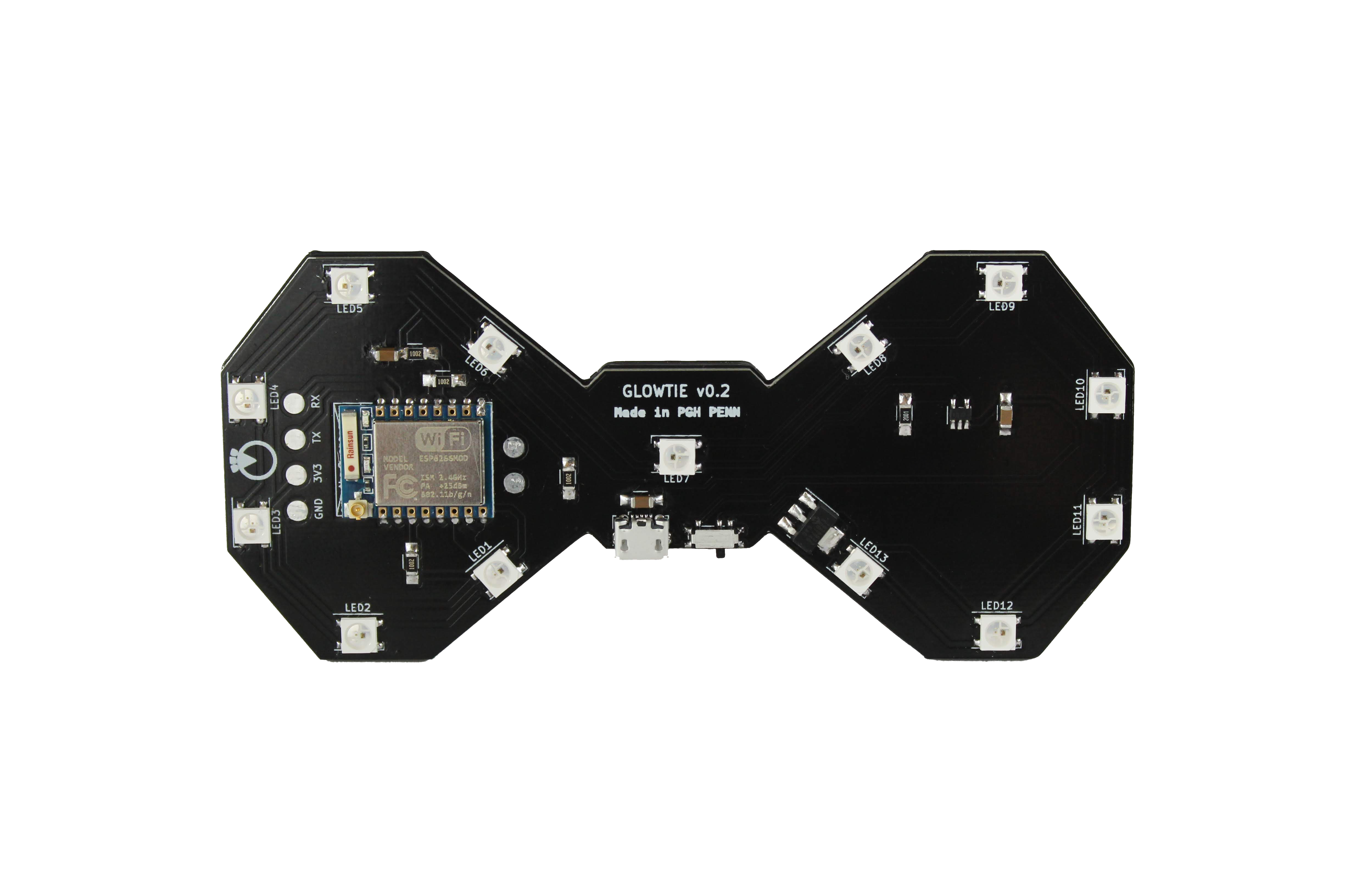
  1. Turn on your Glowtie. There’s a power switch next to the micro usb jack. You should see a gold burst animation; this means the Wifi network has started.
  2. On your Android phone, turn off your mobile data. This is so that your phone doesn’t try to reach the actual internet instead of the Glowtie.
  3. Open your Wifi settings and look for a network named in the format “AdjectiveClothing”. For example, it could be “FancyPants” or “CoolCoat”. This is the Serial Name of your Glowtie. Connect to the network.
  4. You may get a notification that the network you connected to does not have internet access, no worries! Just choose the option to stay connected if you are provided with one.
  5. Now open a new tab in Google Chrome and enter the following in the address field: http://192.168.4.1
  6. You should see the Glowtie control page! In your Chrome settings, choose to “Add to Home screen” to make it easier to get to in the future.

iPhone

  1. Turn on your Glowtie. You should see a gold burst animation; this means the Wifi network has started.
  2. On your iPhone, navigate to Settings -> Cellular and toggle Cellular Data off. This is so that your phone doesn’t try to reach the actual internet instead of the Glowtie.
  3. Open your Wifi settings and look for a network named in the format “AdjectiveClothing”. For example, it could be “FancyPants” or “CoolCoat”. This is the Serial Name of your Glowtie. Connect to the network.
  4. You may get a notification that the network you connected to does not have internet access, no worries! Just choose the option to stay connected if you are provided with one.
  5. Now open a new tab in Safari or Google Chrome and enter the following in the address field: http://192.168.4.1
  6. You should see the Glowtie control page! In your Chrome settings, choose to “Add to Home screen” to make it easier to get to in the future. In Safari, tap the share button and select “Add to Home Screen” to do the same.

Usage

When you load the Glowtie website, you’ll see three sliders. These represent the red, green, and blue values of the lights. When you adjust them, the title background will adjust to show you what color you’re set to.

Once you pick a color, there’s a few options for animations. Tap the button next to the animation you want, then hit the “UPDATE” button. Your Glowtie will change to whatever you selected!

The Glowtie has a built-in memory function, so once you choose a color and animation it’ll remember your choice after you turn it off. This way, you don’t need to connect to it every time you turn it on if you have it set to your favorite pattern.

Charging

When the Glowtie has low battery, the center LED will turn red. Use a Micro USB cable to recharge your Glowtie. Make sure your Glowtie is turned off, then plug the Micro USB cable into the port next to the power switch. When you plug the other end into a USB port for power, you should see the top light on your Glowtie illuminate. When it’s done charging, the bottom light will illuminate.

Cover

Your Glowtie optionally has a diffusion cover. The cover is held on with a friction fit. Laser cut or print diffusion.dxf in a white or clear material, 1/16" thick. Print bumper.stl in a color of your choice, and super glue the diffusion inside the bumper. The bumper can now be friction fit onto the Glowtie.

HACK!

The Glowtie is totally open-source. All PCB design files, firmware, and physical parts are hosted on the Github page. There’s a dedicated programming header on the left side so you can add your own animations, or make it do anything you want! Just solder on a few pins and reprogram the ESP8266 over UART.

Parts

4
QtyValueFootprintReferences
1Conn_01x05_FemalePin_Headers:Pin_Header_Straight_1x05_Pitch2.54mmJ1
1Conn_01x06_FemalePin_Headers:Pin_Header_Straight_1x06_Pitch2.54mmJ2
1LOGOstephen:stephenEmblemBiggerCopperG***
1SW_SPDTButtons_Switches_SMD:SW_SPDT_PCM12SW1

More from sphawes/glowtie

4
  • 2 layers127 × 57.1 mmGlowtie, the printed circuit board in 3D

    Glowtie

    sphawes/glowtie

    The light-up bowtie you control over Wifi

    56 parts25
  • 2 layers127 × 57.1 mmGlowtie, the printed circuit board in 3D

    Glowtie

    sphawes/glowtie

    The light-up bowtie you control over Wifi

    42 parts25
  • 2 layers127 × 57.1 mmGlowtie, the printed circuit board in 3D

    Glowtie

    sphawes/glowtie

    The light-up bowtie you control over Wifi

    41 parts25
  • 2 layers127 × 57.1 mmGlowtie, the printed circuit board in 3D

    Glowtie

    sphawes/glowtie

    The light-up bowtie you control over Wifi

    39 parts25

Similar boards

  • 2 layers18.5 × 26 mm24g2usb rp2350zero, the printed circuit board in 3D

    24g2usb rp2350zero

    joypad-ai/joypad-os

    Universal controller firmware for building adapters, dongles, and custom controllers.

    4 parts1.7kApache-2.0
  • 2 layers116 × 33 mm966595-1 and 963356-1, the printed circuit board in 3D

    966595-1 and 963356-1

    rusefi/rusefi

    rusefi - GPL internal combustion engine control unit

    4 parts1.2k
  • 2 layers19 × 18 mmDaughter board, the printed circuit board in 3D

    Daughter board

    hackclub/OnBoard

    💡 Join 1,000 teenagers and make your first PCB with a $100 grant!

    4 parts915
  • 2 layers24.8 × 24.8 mmNrf24 breakout, the printed circuit board in 3D

    Nrf24 breakout

    tardate/LittleArduinoProjects

    a collection of "Little Electronic & Arduino Projects", most involving electronics or an Arduino in one way or another!

    4 parts803MIT
  • 2 layers26 × 20 mmCap chain, the printed circuit board in 3D

    Cap chain

    drandyhaas/KiCadRoutingTools

    A set of Python/Rust tools to aid routing in KiCad

    4 parts744MIT
  • 2 layers34.7 × 20 mmXG Station Power MSI, the printed circuit board in 3D

    XG Station Power MSI

    osy/XG_Mobile_Station

    Open source eGPU dock for ROG Ally and ROG Flow

    4 parts712CC-BY-4.0
  • 2 layers20.3 × 24.5 mmJack power input, the printed circuit board in 3D

    Jack power input

    Luos-io/luos_engine

    Open-source and real-time orchestrator for cyber-physical-systems, to easily design, test and deploy embedded applications and digital twins.

    4 parts546MIT

Questions

How big is the GlowtieProgrammer PCB?

It measures 59.7 × 40 mm and has 2 copper layers, 1.6 mm thick.

What parts does the GlowtieProgrammer use?

4 parts. The full list of its parts is on this page, with links to each part's symbol and footprint where PCBKit's library has them.

Where can I download the GlowtieProgrammer KiCad files?

From the sphawes/glowtie repository on GitHub, at the commit this page was made from: the board is programmer/pcb/v0.4/glowtieProgrammer/glowtieProgrammer.kicad_pcb and its schematic pcb/V1.0/glowtie.kicad_sch. PCBKit opens the board in the browser, with nothing to install.

Can I use the GlowtieProgrammer design in my own project?

Its repository states no licence, so its author keeps all rights: ask sphawes before reusing the design.