4 layers40 × 60 mm
Control board v2.0
0x23/nmWave-Interferometer
An Open Source Interferometer for Accurate Distance Measurements
106 parts151MIT

 SP6GK/Crowbar3
Complete crowbar PCB for protection of 13.8 V equipment from overvoltage. Suitable for use with solid state 100 W transceivers.
Crowbar is an open-source printed circuit board by SP6GK, from the SP6GK/Crowbar repository on GitHub, published under the GPL-3.0 licence. It is a 2-layer board of 94 × 59 mm with 20 parts on 5 nets, routed with 16 tracks and 158 vias.
It is built around the AMT0450001DB0000G, 1.5SMCJ15CA and BCX56. Its parts include 5 capacitors, 4 resistors, 4 connectors, 3 diodes and 1 transistor. It belongs with the radio and wireless boards of this library.


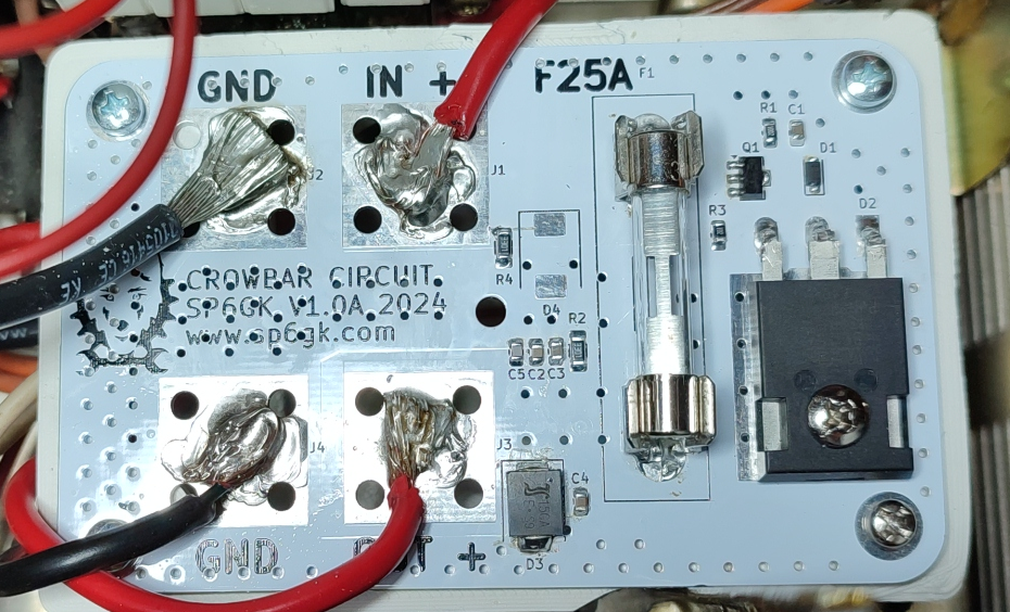
This circuit is designed for overvoltage protection of amateur radio transceivers, which are typically powered by 13.8 V DC with a current of 20 to 25 A.
The protection is achieved by shorting the power supply, which should blow a fuse and prevent expensive equipment from experiencing a voltage spike. The tripping voltage is approximately 14.7 V, but it can be adjusted by replacing the Zener diode.
For low idle current and fast activation of the triac's gate, the circuit uses an additional transistor in a configuration similar to a Zener-NPN regulator.
The PCB features space for M5 screw terminals, but wires can also be soldered directly and four M3 mounting screws.
Recommended Use:
This circuit is especially useful for linear power supplies. In the event of a final transistor(s) fault, a short between the emitter and collector could result in the full rectified voltage being present at the output, which would exceed 13.8 V.
Below is the layout of the PCB:
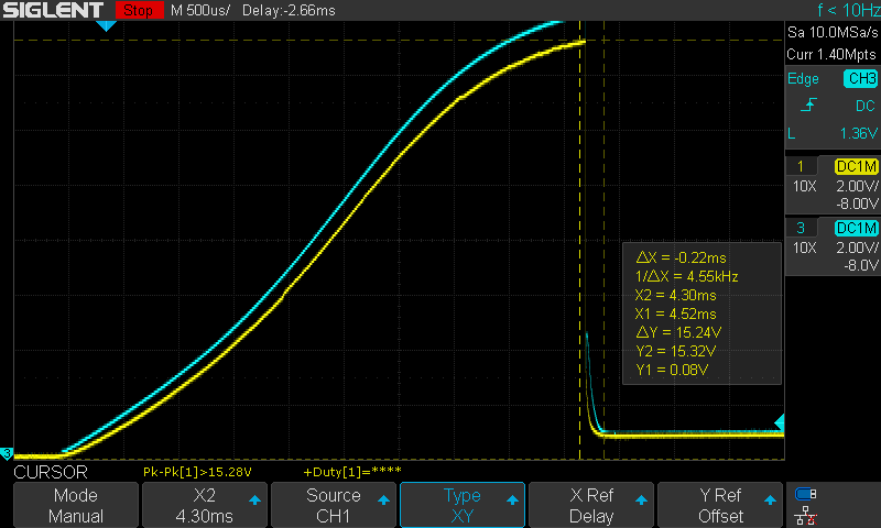
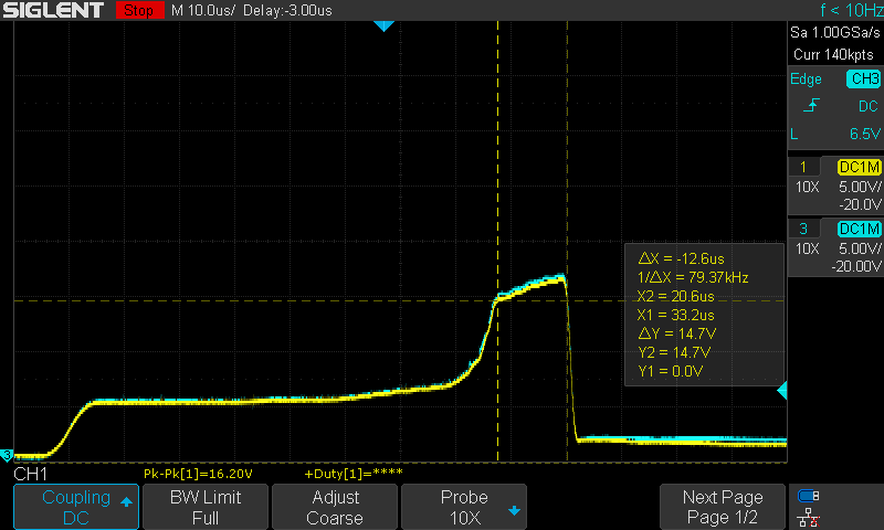
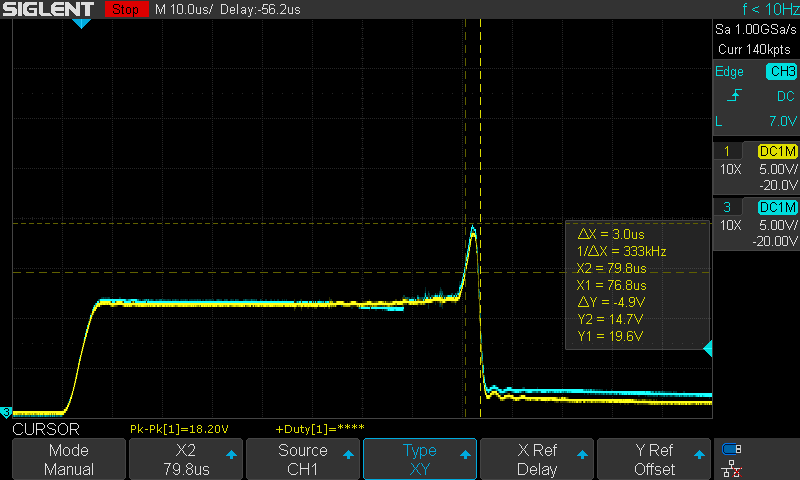
The oscilloscope captures below demonstrate the input (blue, CH2) and output (yellow, CH1) when a sudden 20 V was applied using two parallel 5 A power supplies.
Generating consistent transients was challenging, but these scenarios show how the circuit prevented the voltage rail from ramping up and successfully clamped the voltage.
Transient 1
Transient 2
Transient 3
| Qty | Value | Footprint | References |
|---|---|---|---|
| 4 | AMT0450001DB0000G | ScrewTerminal_custom:AMT0450001DB0000G | J1, J2, J3, J4 |
| 3 | 100n | Capacitor_SMD:C_0805_2012Metric | C1, C2, C4 |
| 2 | 4k7 | Resistor_SMD:R_1206_3216Metric_Pad1.30x1.75mm_HandSolder | R2, R4 |
| 2 | LOGO | logo14 | G***, G*** |
| 1 | 1.5SMCJ15CA | Diode_SMD:D_SMC | D3 |
| 1 | 10k | Resistor_SMD:R_0805_2012Metric_Pad1.20x1.40mm_HandSolder | R3 |
| 1 | 10n | Capacitor_SMD:C_0805_2012Metric | C5 |
| 1 | 15V | Diode_SMD:D_SOD-123F | D1 |
| 1 | 1k | Resistor_SMD:R_0805_2012Metric_Pad1.20x1.40mm_HandSolder | R1 |
| 1 | 1u | Capacitor_SMD:C_0805_2012Metric | C3 |
| 1 | 25 A Fast | Fuse_custom:8040.0001SCHURTER | F1 |
| 1 | BCX56 | Package_TO_SOT_SMD:SOT-89-3 | Q1 |
| 1 | BT155W | Package_TO_SOT_THT:TO-247-3_Horizontal_TabDown | D2 |
It measures 94 × 59 mm and has 2 copper layers, 1.6 mm thick.
20 parts, built around the AMT0450001DB0000G, 1.5SMCJ15CA and BCX56. The full list of its parts is on this page, with links to each part's symbol and footprint where PCBKit's library has them.
From the SP6GK/Crowbar repository on GitHub, at the commit this page was made from: the board is CrowBar.kicad_pcb and its schematic CrowBar.kicad_sch. PCBKit opens the board in the browser, with nothing to install.
Its repository publishes it under the GPL-3.0 licence: you may reuse it on that licence's terms (keep the author's notice, and for a copyleft licence share your changes alike).
0x23/nmWave-Interferometer
An Open Source Interferometer for Accurate Distance Measurements


basson/qym-solder
QymSolder - Soldering station three in one - hakko t12, hot air gun, d909/898D or analog.


NickNifontov/CipollinoRTOS
Sin wave invertor (HRPWM, 35kHz). Replacement for TL/EG PWM .

