
2 layers327.9 × 139 mm
Coco2
baldengineer/bit-preserve
Project for capturing vintage, classic, aka old computer schematics in KiCad.
147 parts446

 souptik-samanta/Blinky
I built this little project because I wanted a heart-shaped PCB that I could gift to someone. It's a simple LED chaser built around a 555 timer and a CD4017 decade counter.
Blinky is an open-source printed circuit board by souptik-samanta, from the souptik-samanta/Blinky repository on GitHub. It is a 2-layer board of 79.4 × 70.5 mm with 20 parts on 18 nets, routed with 83 tracks and 13 vias.
It is built around the NE555P. Its parts include 10 diodes, 2 capacitors, 2 resistors, 2 ICs and 1 connector.
Made by Souptik!
I built this little project because I wanted a heart-shaped PCB that I could gift to someone. It's a simple LED chaser built around a 555 timer and a CD4017 decade counter. The LEDs light up one after another, creating a blinking animation around the heart.
Built using parts I already had on hand, and manufactured through JLC thanks stasis.
BUILD PHOTO
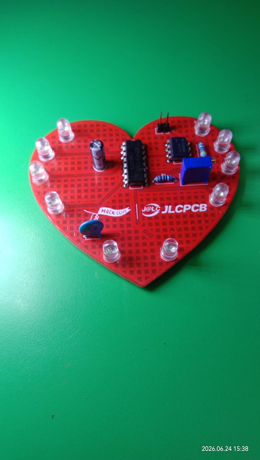
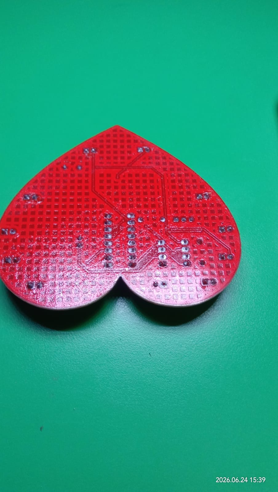
and here is the bottom
worknig video
https://youtube.com/shorts/QsSJmAaTk8Q?feature=share
A 555 timer is configured as an oscillator that generates clock pulses. These pulses are fed into a CD4017 decade counter, which turns on one output at a time. Each output drives an LED on the heart, creating a rotating blinking effect. The potentiometer can be adjusted to change the animation speed.
| Part | Purpose | Quantity |
|---|---|---|
| PCB | Heart-shaped board that holds all the components | 1 |
| LED | Creates the chasing light effect around the heart | 10 |
| 1kΩ Resistor | Helps set the oscillator timing | 1 |
| 470Ω Resistor | Limits LED current | 1 |
| Potentiometer (RV) | Adjusts the animation speed | 1 |
| 1µF Capacitor | Works with the 555 timer to generate clock pulses | 1 |
| 1x01 Header | Test/debug connection point | 1 |
| 1x02 Header | Power input connector | 1 |
| CD4017 | Sequences the LEDs one after another | 1 |
| NE555P | Generates the clock signal | 1 |
All components were sourced from my existing parts inventory, so the project itself cost me nothing to assemble.
| Item | Cost (USD) |
|---|---|
| Components | $0.00 |
| PCB | JLC sponser |
| Total Out-of-Pocket Cost | $0.00 |
I wanted to make something small, simple, and fun that could be gifted to someone. Instead of a regular rectangular PCB, I designed it in the shape of a heart and added a classic 555 + 4017 LED chaser circuit to make it feel a bit more special.
| Qty | Value | Footprint | References |
|---|---|---|---|
| 10 | LED | LED_THT:LED_D5.0mm | D1, D2, D3, D4, D5, D6, D7, D8, D9, D10 |
| 2 | LOGO | LOGO | G***, G*** |
| 1 | 0.1uF | Capacitor_THT:C_Disc_D4.7mm_W2.5mm_P5.00mm | C2 |
| 1 | 100uF | Capacitor_THT:CP_Radial_D5.0mm_P2.50mm | C1 |
| 1 | 4017 | Package_DIP:DIP-16_W7.62mm_LongPads | U1 |
| 1 | 470 | Resistor_THT:R_Axial_DIN0207_L6.3mm_D2.5mm_P7.62mm_Horizontal | R2 |
| 1 | Conn_01x02_Pin | Connector_PinSocket_2.54mm:PinSocket_1x02_P2.54mm_Vertical | J1 |
| 1 | NE555P | Package_DIP:DIP-8_W7.62mm_LongPads | U2 |
| 1 | R | Resistor_THT:R_Axial_DIN0207_L6.3mm_D2.5mm_P7.62mm_Horizontal | R1 |
| 1 | R_Potentiometer | Potentiometer_THT:Potentiometer_Vishay_T93YA_Vertical | RV1 |
baldengineer/bit-preserve
Project for capturing vintage, classic, aka old computer schematics in KiCad.

The-Invent0r/8-bit-Computer-PCB
These are the KiCAD files for my 8-Bit Computer.

DarcyJProjects/touchtone555
An open-source DIY, NE555-based analogue synthesizer - play notes with a stylus


benjiaomodular/SynthCard
I designed this project with the help of PCBWay. You can get a copy of these cards through the PCBWay Shared Projects page.

fortinsylvain/MyCpu
Home brew CPU Hardware with 1-bit ALU implementation using 74LSxx, a micro-code and assembler coded in C#.

hackup/C128Diag
Replica of the Commodore C128 Diagnostic Test cartridge Assy No. 325093-01.
It measures 79.4 × 70.5 mm and has 2 copper layers, 1.6 mm thick.
20 parts, built around the NE555P. The full list of its parts is on this page, with links to each part's symbol and footprint where PCBKit's library has them.
From the souptik-samanta/Blinky repository on GitHub, at the commit this page was made from: the board is PCB/project.kicad_pcb and its schematic PCB/project.kicad_sch. PCBKit opens the board in the browser, with nothing to install.
Its repository states no licence, so its author keeps all rights: ask souptik-samanta before reusing the design.