4 layers30 × 30 mm

 someonelse20/farsight-rc
Custom remote controler with esp32 to stream telemetry.
Controller is an open-source printed circuit board by someonelse20, from the someonelse20/farsight-rc repository on GitHub. It is a 2-layer board of 125 × 95 mm with 66 parts on 72 nets, routed with 483 tracks and 227 vias.
It is built around the ESP32-S3-MINI-1-N8, AMS1117-3.3 and BQ25895RTW, with the THB001P and AO3401A among its other parts. Its parts include 24 resistors, 17 capacitors, 5 connectors, 5 switches and 3 ICs. It belongs with the ESP32 boards of this library.


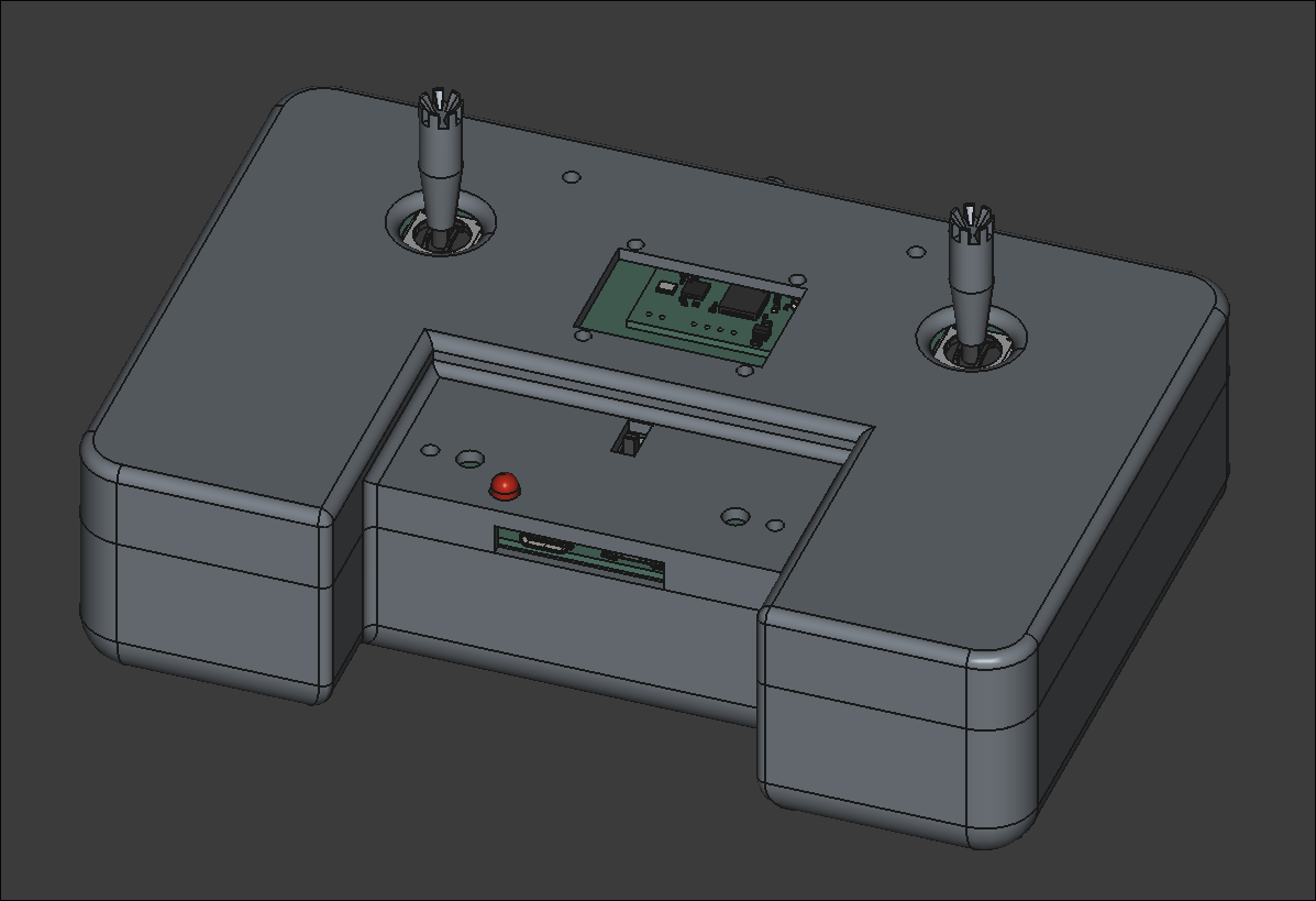
Custom long range remote controller with ESP32 to stream telemetry and an STM32 based lora module with the SX1262. The controller has a build in 18650 battery with an integrated charger. The transceiver is its own standalone board and can be used independenly of the controller. I made this project as a part of my larger goal to make a custom drone. I originally was going to make it out of stock modules but decided to design custom pcbs.
--This is still under development and is subject to change--
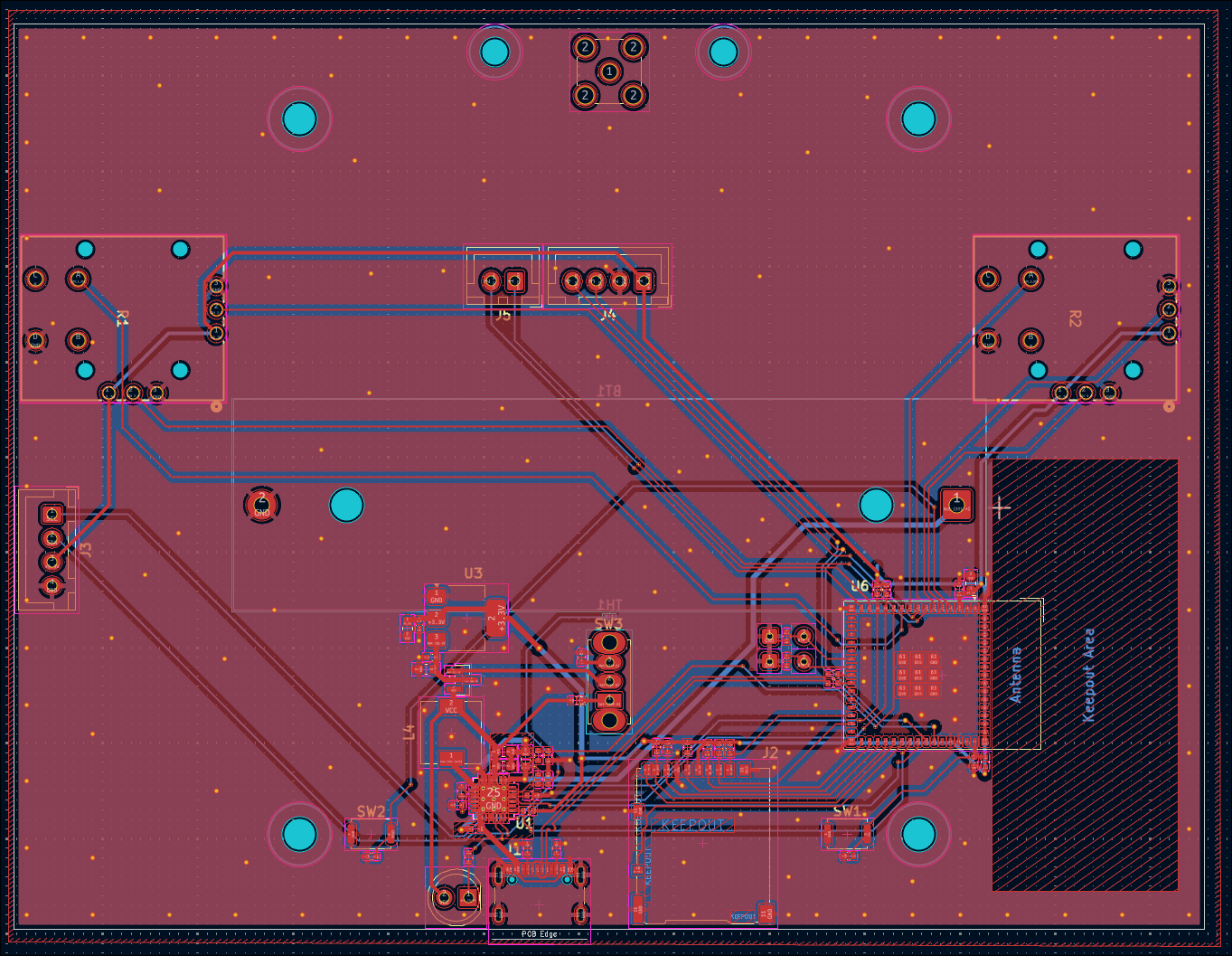
The switch in the middle of the controller is the power switch and the led is the status of the battery charging. The usb connecter will charge the battery and can be used to communicate with the ESP32. The micro SD card will log all the incoming telemetry.
The controller software is currently pretty basic and missing some fetures. The wifi network the esp32 will create can be configured by installing the espressive ide and running idf.py menuconfig and changing the wifi ssid and password under Wifi Configuration. Requesting /telemetry of the ip of the nextork will return a set of comma separated values in the format of "altitude_meters,speed_meters_per_second,heading_degrees,latitude,longitude".
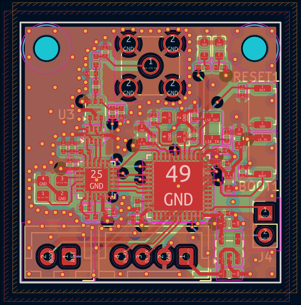
UART pinout:
| 1 | 2 | 3 | 4 |
|---|---|---|---|
| VCC | GND | RX | TX |
Microcontroller pinout:
| 1 | 2 |
|---|---|
| RESET | BOOT |
Debug pinout:
| 1 | 2 |
|---|---|
| SWDCLK | SWDIO |
The transceiver has an internal regulator and can handle up to 5v input. The UART pinout is from the transceiver reference so an external device would put its Tx to the transceiver Rx and vice versa. The buttons on the board will put the STM32 into boot and reset mode respectively and the external pins are directly wired to the microcontroller.
The transceiver is built on the Semtech SX1262 driver. To communicate with the transceiver a host must first send a register bit and then the data to transmit or receive based on the table below.
| Address | Name | Description | Input/Output | Size | Note |
|---|---|---|---|---|---|
| 0 | who_am_i | Device ID | O | 1 | Device ID is 126 |
| 1 | TX | Transmits packet | I | - | First send size byte then send data byte. |
| 2 | RX | Receives packet | I/O | - | First send size byte then send data byte. |
| 3 | TX_set | Transmits packet | I | - | Packet size must always be payload_len. |
| 4 | RX_set | Receives packet | O | - | Packet size must always be payload_len. |
| 5 | sleep | Puts transceiver into sleep mode | - | 0 | |
| 6 | wakeup | Wakes up transceiver | - | 0 | |
| 7 | set_all | Inputs a setting struct | I | TBD | See settings_t |
| 8 | set_frequency | Sets SX1262 frequency | I | 4 | See sx126x_set_rf_freq |
| 9 | set_tx_params | Sets SX1262 TX power and ramp time | I | 2 | array of {power in dBm, ramp time (see datasheet)} |
| 10 | set_lora_mod_params | Sets LoRa parameters | I | TBD | See sx126x_mod_params_lora_t |
| 11 | set_lora_pkt_params | Sets LoRa packet parameters | I | TBD | See sx126x_pkt_params_lora_t |
| 12 | set_lora_symb_nb_timeout | Sets loRa timeout in symbols | I | 1 | See sx126x_set_lora_symb_nb_timeout |
| 13 | set_encrypt_params | Sets encryption parameters | I | - | Not currently implemented |
| 14 | enable_encrypt | Enables/disables encryption | I | - | Not currently implemented |
TBD means that the size is based on the size of a struct which will be calculated when I can run the code on the hardware.
BOM to make two transceivers and two controllers but with only two antennas and one micro SD card. All prices in USD. Price column is total price and does not include shipping.
| Qty | Value | Footprint | References |
|---|---|---|---|
| 11 | 10K | Resistor_SMD:R_0402_1005Metric | R3, R5, R6, R7, R8, R9, R10, R16, R17, R18, R21 |
| 7 | 0.1uF | Capacitor_SMD:C_0402_1005Metric | C1, C2, C5, C13, C14, C23, C26 |
| 3 | 10uF | Capacitor_SMD:C_0603_1608Metric | C20, C21, C22 |
| 3 | 22uF | Capacitor_SMD:C_0603_1608Metric | C6, C17, C18 |
| 3 | 5.1K | Resistor_SMD:R_0402_1005Metric | R11, R12, R15 |
| 2 | 100 | Resistor_SMD:R_0402_1005Metric | R4, R27 |
| 2 | 1uF | Capacitor_SMD:C_0402_1005Metric | C4, C15 |
| 2 | 27 | Resistor_SMD:R_0402_1005Metric | R25, R26 |
| 2 | THB001P | controller:THB001P_CNK | R1, R2 |
| 1 | 2.2uH | Inductor_SMD:L_6.3x6.3_H3 | L4 |
| 1 | 200 | Resistor_SMD:R_0402_1005Metric | R19 |
| 1 | 30.1K | Resistor_SMD:R_0402_1005Metric | R14 |
| 1 | 4.7uF | Capacitor_SMD:C_0402_1005Metric | C19 |
| 1 | 47nF | Capacitor_SMD:C_0402_1005Metric | C16 |
| 1 | 5.2K | Resistor_SMD:R_0402_1005Metric | R13 |
| 1 | 5.5K | Resistor_SMD:R_0402_1005Metric | R22 |
| 1 | AMS1117-3.3 | Package_TO_SOT_SMD:SOT-223-3_TabPin2 | U3 |
| 1 | AO3401A | Package_TO_SOT_SMD:SOT-23 | Q1 |
| 1 | BQ25895RTW | Package_DFN_QFN:Texas_RTW_WQFN-24-1EP_4x4mm_P0.5mm_EP2.7x2.7mm_ThermalVias | U1 |
| 1 | BTN_1 | Connector_Wire:SolderWire-0.1sqmm_1x02_P3.6mm_D0.4mm_OD1mm | SW4 |
| 1 | BTN_2 | Connector_Wire:SolderWire-0.1sqmm_1x02_P3.6mm_D0.4mm_OD1mm | SW5 |
| 1 | Battery | Battery:BatteryHolder_MPD_BH-18650-PC | BT1 |
| 1 | Boot | Button_Switch_SMD:SW_Push_SPST_NO_Alps_SKRK | SW2 |
| 1 | Display | Connector_JST:JST_XH_B4B-XH-A_1x04_P2.50mm_Vertical | J3 |
| 1 | ESP32-S3-MINI-1 | RF_Module:ESP32-S2-MINI-1 | U6 |
| 1 | LED | LED_THT:LED_D5.0mm | D1 |
| 1 | Micro_SD_Card_Det_Hirose_DM3AT | Connector_Card:microSD_HC_Hirose_DM3AT-SF-PEJM5 | J2 |
| 1 | Reset | Button_Switch_SMD:SW_Push_SPST_NO_Alps_SKRK | SW1 |
| 1 | SW_SPDT | Button_Switch_THT:SW_Slide_SPDT_Straight_CK_OS102011MS2Q | SW3 |
| 1 | Thermistor | Resistor_SMD:R_0402_1005Metric | TH1 |
| 1 | Tranceiver Boot/Rst | Connector_JST:JST_XH_B2B-XH-A_1x02_P2.50mm_Vertical | J5 |
| 1 | Tranceiver Data | Connector_JST:JST_XH_B4B-XH-A_1x04_P2.50mm_Vertical | J4 |
| 1 | USB_C_Receptacle_USB2.0_16P | Connector_USB:USB_C_Receptacle_GCT_USB4105-xx-A_16P_TopMnt_Horizontal | J1 |
The 59 most common of 66 parts.
It measures 125 × 95 mm and has 2 copper layers, 1.6 mm thick.
66 parts, built around the ESP32-S3-MINI-1-N8, AMS1117-3.3, BQ25895RTW and THB001P. The full list of its parts is on this page, with links to each part's symbol and footprint where PCBKit's library has them.
From the someonelse20/farsight-rc repository on GitHub, at the commit this page was made from: the board is hardware/controller/controller.kicad_pcb and its schematic hardware/controller/controller.kicad_sch. PCBKit opens the board in the browser, with nothing to install.
Its repository states no licence, so its author keeps all rights: ask someonelse20 before reusing the design.


Nicolai-Electronics/tanmatsu-hardware
Hardware design of the Tanmatsu mainboard

borisg912/3DNA
This project creates a flat cylindrical DNA model with: - Magnetic DNA bases with color-coded NeoPixel LEDs and unique resistor values for identification - Interactive base pairing game that validates correct DNA base…

frahncky/Smart-Metering
Analisador trifásico de energia e qualidade de energia com interface gráfica touchscreen.

JamesTwallin/gas_sensor
A tiny plug-in board for the rev E phone-companion board. It stands upright in a notch in rev E's sensor end, between the two gas sensor cans, and pokes 4.5 mm out through a slot in the case face, so its tip sits in the…
