2 layers
 solarcaratuva/EmbeddedSystem7
UVA Solar Car Embedded Systems PCB design and ECU code
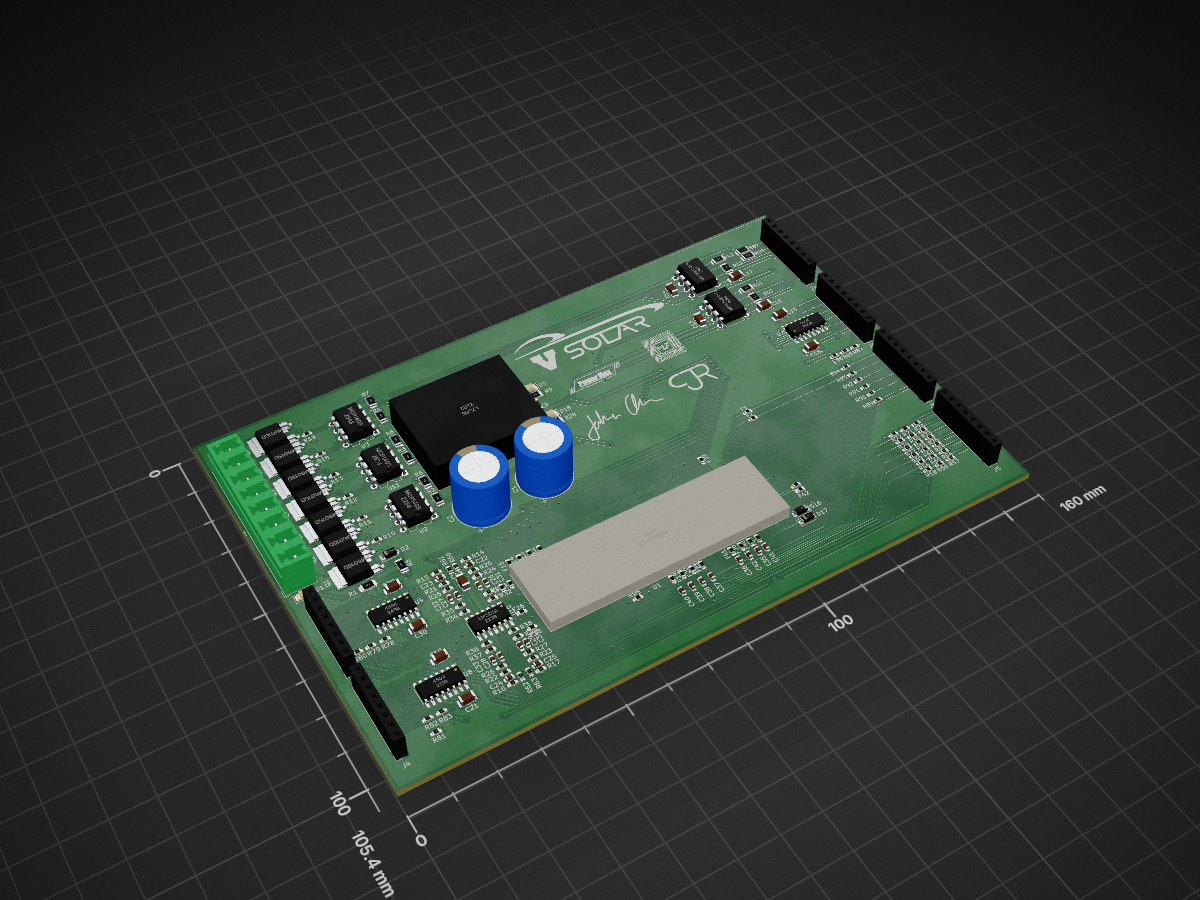
SolarCarECU is an open-source printed circuit board by solarcaratuva, from the solarcaratuva/EmbeddedSystem repository on GitHub. It is a 4-layer board of 160 × 105.4 mm with 231 parts on 210 nets, routed with 1,343 tracks and 201 vias.
It is built around the LM324AD, MCP1403-E/P and L7805. Its parts include 95 resistors, 44 capacitors, 44 fuses, 18 diodes and 11 ICs. It belongs with the NXP (LPC, Kinetis, i.MX RT) boards of this library.


The embedded system sub-group focuses on developing the embedded system for the solar car that controls the CAN bus, driver interface and BPS (Battery Management System). This repository contains all of the design files necessary to implement the electrical control systems necessary for the Solar Car project.
The ECU is the primary controller for the majority of systems, including motor control, battery monitoring, driver interface, and MPPT interface. The PCB contains circuitry for interfacing buttons and switches on driver interface, high-current lights and horn, as well as
!important! Not all pins are 12V or even 5V compatible. Certain pins connect directly to the teensy with no protection.
These pins are used for allowing the driver to command the vehicle. All but the UART pins are 12V logic. To reduce the number of pins required on the MCU, we chose to wire 3 way position switches such that the end contacts connect to the rails and the center contact floats with a resistor divider to ensure the voltage is approximately VCC/2 when the switch is in the middle position.
| signal | pin | voltage | direction | description |
|---|---|---|---|---|
| BRAKE_CTRL | 20 | 0 - 12V | input | brake potentiometer, used to implement regen |
| REGEN_CTRL | 17 | 0 - 12V | input | regen potentiometer, used to set max regen percentage |
| GEARSHIFT_CTRL | 14 | 0 - 12V | input | 3 way position switch. 12V = forward, 6V = neutral, 0V = reverse |
| TURNSIG_CTRL | 15 | 0 - 12V | input | 3 way position switch. 12V = forward, 6V = neutral, 0V = reverse |
| THROTTLE_CTRL | 16 | 0 - 12V | input | throttle potentiometer, the gas petal |
| STEER_CTRL | 21(A7) | 0 - 12V | input | potentiometer on steering wheel, may be used for differential throttle control |
| HAZARD_CTRL | 16 | 0 - 12V | input | pushbutton used to activate hazard lights, toggles on changing edge |
| HORN_CTRL | 22(A6) | 0 - 12V | input | horn button |
| DOWN_CTRL | 26 | 0 - 12V | input | GUI navigation pushbutton |
| UP_CTRL | 27 | 0 - 12V | input | GUI navigation pushbutton |
| SEL_CTRL | 28 | 0 - 12V | input | GUI navigation pushbutton |
| KILL_SENSE | 2 | 0 - 12V | input | used to detect if the power engaging the relays has been cut |
| HAZARD_LED | 25 | 0 - 12V | output | connected to hazard button LED |
| UART_1_RX | 0 | 0 - 3.3V | input | used for Nextion 3.2" LCD |
| UART_1_TX | 1 | 0 - 3.3V | output | used for Nextion 3.2" LCD |
These pins are used for communicating with various peripherals, components, and subsystems within the car. CAN0 is reserved for the BMS, while CAN1 is used for all less critical systems. UART pins are for future use.
| signal | pin | voltage | direction | description |
|---|---|---|---|---|
| CAN0_H | 0 - 5V | CAN high | connected to CAN0 peripheral on Teensy 3.6 through MCP2562 | |
| CAN0_L | 0 - 5V | CAN low | connected to CAN0 peripheral on Teensy 3.6 through MCP2562 | |
| CAN1_H | 0 - 5V | CAN high | connected to CAN1 peripheral on Teensy 3.6 through MCP2562 | |
| CAN1_L | 0 - 5V | CAN low | connected to CAN1 peripheral on Teensy 3.6 through MCP2562 | |
| UART_3_RX | 7 | 0 - 3.3V | input | reserved for future use |
| UART_3_TX | 8 | 0 - 3.3V | output | reserved for future use |
| UART_6_RX | 47 | 0 - 3.3V | input | reserved for future use |
| UART_6_TX | 48 | 0 - 3.3V | output | reserved for future use |
These pins are capable of high currents (up to 5A distributed among the 4 outputs)
| signal | pin | voltage | direction | description |
|---|---|---|---|---|
| HORN | 57 | 0 - 12V | output | high power output for car horn (can only source current) |
| HEADLIGHTS | 42 | 0 - 12V | output | high power output for headlights (can only source current) |
| BRAKELIGHTS | 56 | 0 - 12V | output | high power output for brakelights (can only source current) |
| STROBE | 6 | 0 - 12V | output | high power output for strobelight (can only source current) |
| RIGHT_BLINKERS | 41 | 0 - 12V | output | high power output for right blinkers (can only source current) |
| LEFT_BLINKERS | 40 | 0 - 12V | output | high power output for left blinkers (can only source current) |
| HORN_CTRL | 22 | 0 - 12V | input | high power input for horn |
| HEADLIGHT_CTRL | 23 | 0 - 12V | input | high power input for headlights |
| BRAKE_CTRL | 20 | 0 - 12v | input | analog input for brakes (used for regen) |
The motor can be interfaced via UART, CAN, and GPIO. As of now, we do not have any API or knowledge of how to interface the motor over UART, as it is not documented. However it is possible to decompile the android app and reverse engineer whatever the app implements. For now, we are using CAN to retrieve important parameters from the motor such as voltage, current, RPM, throttle, and error codes. The motor only outputs messages over CAN, and does not interpret them.
The table below holds true for both MOTOR_R* and MOTOR_L* signals.
NOTE: all node names in the table below are preceded with MOTOR_R* and MOTOR_L*!
| signal | pin (L) | pin (R) | voltage | direction | description |
|---|---|---|---|---|---|
| REGEN_EN | 50 | 53 | 0 - 12V | output | enables regenerative braking on motor controller |
| REGEN | 36(pwm) | 37(pwm) | 0 - 5V | output | analog output sets regen level when throttle is disabled (????) |
| THROTTLE | 35(pwm) | 38(pwm) | 0 - 5V | output | sets throttle when FWD_EN or REV_EN are enabled. |
| ECO_EN | 49 | 39 | 0 - 12V | output | Reduces maximum power of motor controller |
| METER | A11 | A10 | 0 - 12V | input | analog output from motor controller (????) |
| FWD_EN | 55 | 52 | 0 - 12V | output | forward enable |
| REV_EN | 54 | 51 | 0 - 12V | output | reverse enable |
At the moment we have bits and pieces of code written but no unified project as of yet. The CAN repository contains experemantal code for interfacing the CAN peripherals on the Teensy as well as development towards a motor driver. The completed motor driver will eventually be refactored into this repo.
| Qty | Value | Footprint | References |
|---|---|---|---|
| 44 | Polyfuse | Fuse:Fuse_0603_1608Metric | F1, F2, F10, F11, F12, F13, F14, F15, F16, F17, F18, F19, F20, F21, F22, F23 +28 |
| 19 | 100k | Resistor_SMD:R_0603_1608Metric | R29, R31, R40, R43, R44, R45, R46, R47, R48, R49, R50, R51, R54, R55, R56, R60 +3 |
| 18 | 1M | Resistor_SMD:R_0603_1608Metric | R30, R57, R58, R64, R65, R67, R68, R70, R71, R73, R75, R76, R78, R79, R81, R82 +2 |
| 14 | D | Diode_SMD:D_SOD-123 | D4, D5, D6, D7, D8, D9, D10, D11, D12, D13, D14, D15, D16, D17 |
| 11 | 100n | Capacitor_SMD:C_1206_3216Metric | C4, C7, C10, C13, C14, C15, C16, C17, C19, C20, C43 |
| 9 | 1n | Capacitor_SMD:C_0603_1608Metric | C35, C36, C37, C38, C39, C40, C41, C42, C44 |
| 9 | 330k | Resistor_SMD:R_0603_1608Metric | R59, R66, R69, R72, R74, R77, R80, R83, R86 |
| 8 | 100k | Resistor_SMD:R_1206_3216Metric | R2, R3, R4, R5, R6, R7, R41, R42 |
| 8 | 1k | Resistor_SMD:R_0603_1608Metric | R32, R33, R34, R35, R36, R37, R38, R39 |
| 7 | QM6015D | Package_TO_SOT_SMD:TO-252-2 | Q1, Q2, Q3, Q4, Q5, Q6, Q7 |
| 6 | 1k | Resistor_SMD:R_1206_3216Metric | R1, R8, R9, R28, R87, R88 |
| 6 | 4.7 | Resistor_SMD:R_0603_1608Metric | R10, R11, R12, R13, R18, R19 |
| 6 | 4.7u | Capacitor_SMD:C_1206_3216Metric | C5, C8, C11, C18, C21, C30 |
| 6 | 47 | Resistor_SMD:R_0603_1608Metric | R89, R90, R91, R92, R93, R94 |
| 6 | Screw_Terminal_01x08 | Connector_PinSocket_2.54mm:PinSocket_1x08_P2.54mm_Vertical | J3, J4, J5, J6, J7, J8 |
| 4 | 120k | Resistor_SMD:R_0603_1608Metric | R20, R21, R22, R23 |
| 4 | 2.2n | Capacitor_SMD:C_0603_1608Metric | C31, C32, C33, C34 |
| 4 | 3.3n | Capacitor_SMD:C_0603_1608Metric | C22, C23, C24, C25 |
| 4 | 36k | Resistor_SMD:R_0603_1608Metric | R24, R25, R26, R27 |
| 4 | 6.8n | Capacitor_SMD:C_0603_1608Metric | C26, C27, C28, C29 |
| 4 | 8.2k | Resistor_SMD:R_0603_1608Metric | R14, R15, R16, R17 |
| 3 | 4504 | Package_SO:SOIC-16_3.9x9.9mm_P1.27mm | U7, U8, U9 |
| 3 | 47u | Capacitor_SMD:C_1206_3216Metric | C6, C9, C12 |
| 3 | MCP1403 | Package_DIP:DIP-8_W7.62mm | U2, U3, U11 |
| 2 | 120 | Resistor_SMD:R_1206_3216Metric | R52, R53 |
| 2 | 470uF | Capacitor_THT:CP_Radial_D13.0mm_P5.00mm | C1, C2 |
| 2 | MCP2562-E-P | Package_DIP:DIP-8_W7.62mm | U5, U6 |
| 1 | 0 | Resistor_SMD:R_0603_1608Metric | R95 |
| 1 | 10uF | Capacitor_SMD:C_1206_3216Metric | C3 |
| 1 | 599-0210 | LED_SMD:LED_1206_3216Metric | D1 |
| 1 | 599-0230 | LED_SMD:LED_1206_3216Metric | D3 |
| 1 | 599-0291 | LED_SMD:LED_1206_3216Metric | D18 |
| 1 | D_Zener | Diode_SMD:D_SOD-123 | D2 |
| 1 | L7805 | PCBDesign:PT78NR112H | U4 |
| 1 | LM324A | Package_SO:SOIC-14_3.9x8.7mm_P1.27mm | U10 |
| 1 | LOGO | logo:PowerMax | G*** |
| 1 | LOGO | logo:JohnC | G*** |
| 1 | LOGO | logo:WZ | G*** |
| 1 | LOGO | logo:CJR | G*** |
| 1 | LOGO | logo:SOLAR | G*** |
| 1 | Screw_Terminal_01x08 | Connector_Phoenix_MC_HighVoltage:PhoenixContact_MCV_1,5_8-G-5.08_1x08_P5.08mm_Vertical | J2 |
| 1 | Teensy3.6 | teensy:Teensy35_36 | U1 |
It measures 160 × 105.4 mm and has 4 copper layers, 1.6 mm thick.
231 parts, built around the LM324AD, MCP1403-E/P and L7805. The full list of its parts is on this page, with links to each part's symbol and footprint where PCBKit's library has them.
From the solarcaratuva/EmbeddedSystem repository on GitHub, at the commit this page was made from: the board is ECU_PCB/SolarCarECU.kicad_pcb. PCBKit opens the board in the browser, with nothing to install.
Its repository states no licence, so its author keeps all rights: ask solarcaratuva before reusing the design.

ProfeRimoldi/Proyecto_CanSAT
Sistema electrónico para misión tipo CanSat desarrollado en la EEST N°4 I Brigada Aérea El Palomar, orientado al diseño, validación y documentación de hardware y firmware para sistemas embarcados aeroespaciales.


ForNextSoftwareDevelopment/8085
Intel 8085 Assembler / Disassembler / SDK-85 Simulator

fer-clerkx/speeduino-expo
Speeduino board using Teensy 4.1 adapted from V0.4.4c design


FontysMinorAR/LevelShifter
This is an application for the Arduino Nano to test the Level shifter Board