2 layers190 × 100 mm

 smaldragon/MicroMicro2
A tiny byte-syzed 65c02 microcomputer
MicroMicro is an open-source printed circuit board by smaldragon, from the smaldragon/MicroMicro repository on GitHub, published under the Unlicense licence. It is a 2-layer board of 190 × 100 mm with 126 parts on 130 nets, routed with 2,042 tracks and 368 vias.
It is built around the 74HCT540D, 74HC590ADW and 74HC10D, with the 74HC14, 74HC166D and 74HC174D among its other parts. Its parts include 41 diodes, 32 switches, 17 capacitors, 12 ICs and 8 resistors.


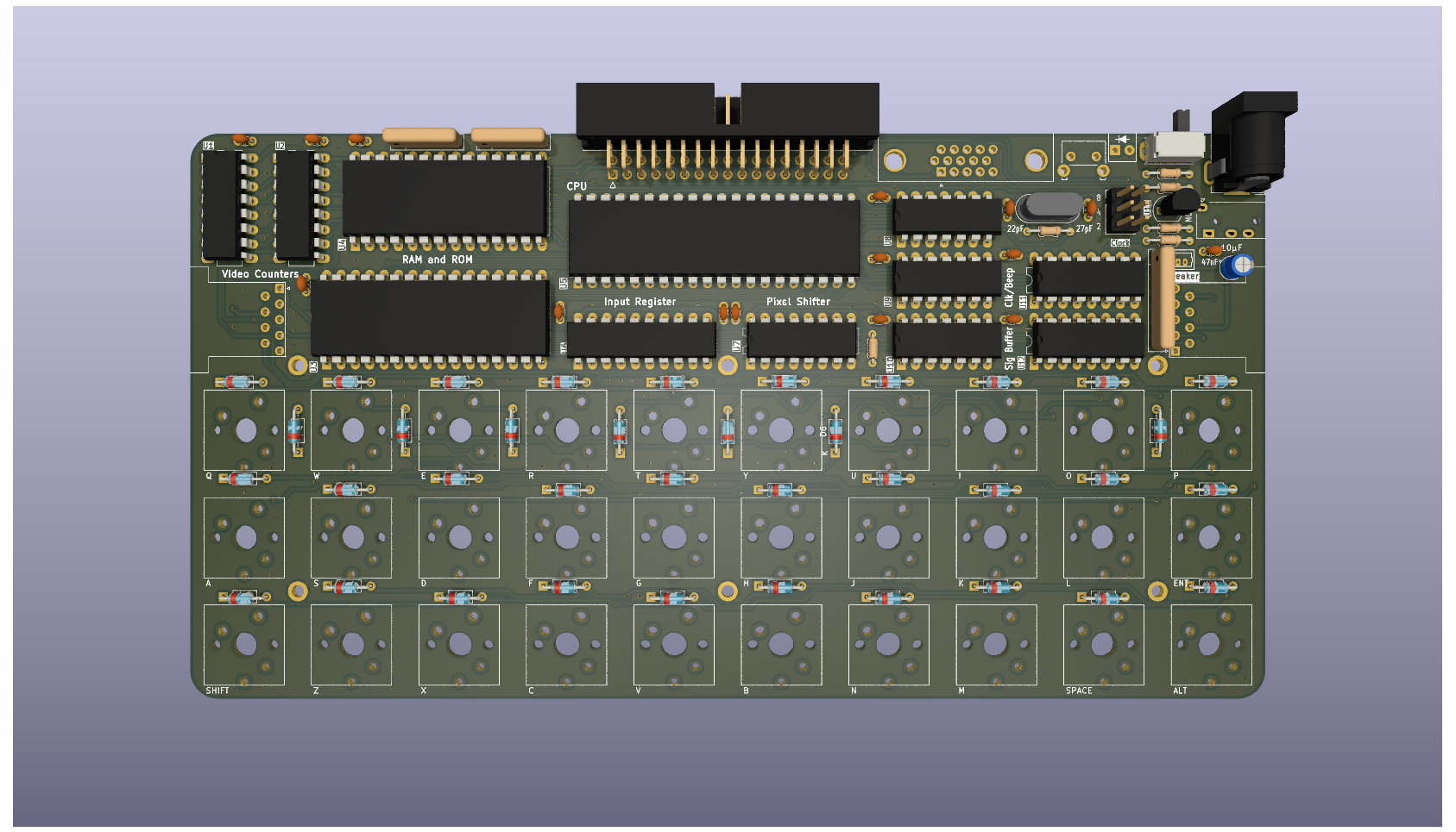
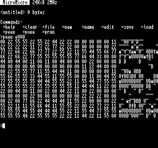
The MicroMicro (working name) is a project designed for a series I inteded(intend) to write, about how microcomputers work and how to go about developing one. It was designed to use a relatively small amount of integrated circuits (13), not use any programmable chips, microcontrollers or obselete parts, and to be a self-contained architecture that handles its own input and output (ie. not serial based).
With these requirements in mind, the overall specs are humble but capable:
Potential Features
The software side is still up in the air, but I'm aiming for the following features:
This code would likely be custom and documented to follow the article structure of the hardware side of things.
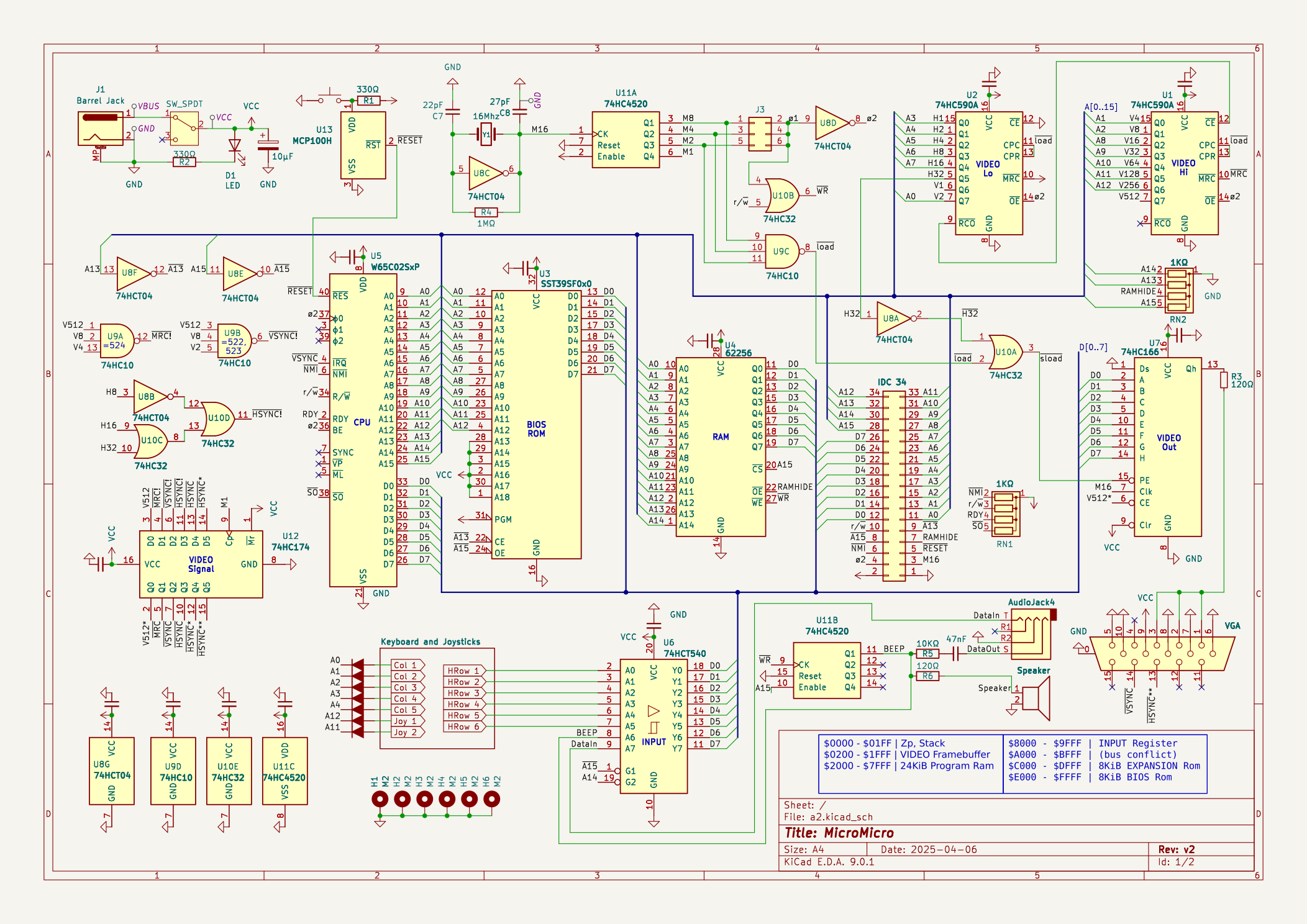
+---------------------+-------+-----------+
| Name                | Size  | Location  |
+---------------------+-------+-----------+
| Zero Page & Stack   | 512   | 0000-01FF |
| Video Data          | 7680  | 0200-1FFF |
| General Purpose RAM | 24576 | 2000-7FFF |
| IO Registers        | 8192  | 8000-9FFF |
| Expansion ROM       | 8192  | C000-DFFF |
| Bios ROM            | 8192  | E000-FFFF |
+---------------------+-------+-----------+
* the area from A000-BFFF is an invalid bus conflict regionEach byte corresonds to a line of 8 horizontal pixels on the screen. The screen addresses are organized as 32x30 character cells of 8x8 pixels each. 8 Consecutive bytes build one character.
This non-linear format was chosen to speed up the rendering of characters to the screen.
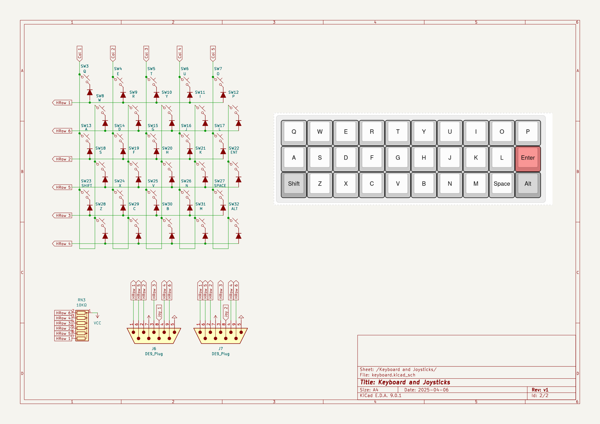
The state of the keyboard and joysticks can be read at the following addresses:
+---------------------+----------+-------------------------+
| Name                | Address  | Value (bits 0-5)        |
+---------------------+----------+-------------------------+
| Keyboard Col 1      |   9FFE   |  Q   A  Shf  z   S   W  |
| Keyboard Col 2      |   9FFD   |  E   D   X   C   F   R  |
| Keyboard Col 3      |   9FFB   |  T   G   V   B   H   Y  |
| Keyboard Col 4      |   9FF7   |  U   J   N   M   K   I  |
| Keyboard Col 5      |   9FEF   |  O   L  SPC ALT ENT  P  |
| Joystick 1          |   8FFF   |  ↑   ↓   ←   →   L   R  |
| Joystick 2          |   97FF   |  ↑   ↓   ←   →   L   R  |
+---------------------+----------+-------------------------+The Beeper is a 1bit register that is used for both audio generation and to load and save programs to tape. It can be accessed through the following registers:
+---------------------+-------------+-----------+
| Name                | Address     | Value     |
+---------------------+-------------+-----------+
| State               | 9FFF (read) | TB.. .... |
| Toggle Beeper       | FFFF (write)| 0000 0000 |
+---------------------+-------------+-----------+
T = Tape Input
B = Beeper State (top 2 bits of input register)
The tape interface is a 4-pin trs connector that be connected directly to a computer using an appropriate aux cable.
Note: While these registers can be accessed from alternative locations, the addresses and values on this table ensure no bus conflicts occur.
The MicroMicro has an expansion interface that allows extending the base capabilities of the system in various ways:
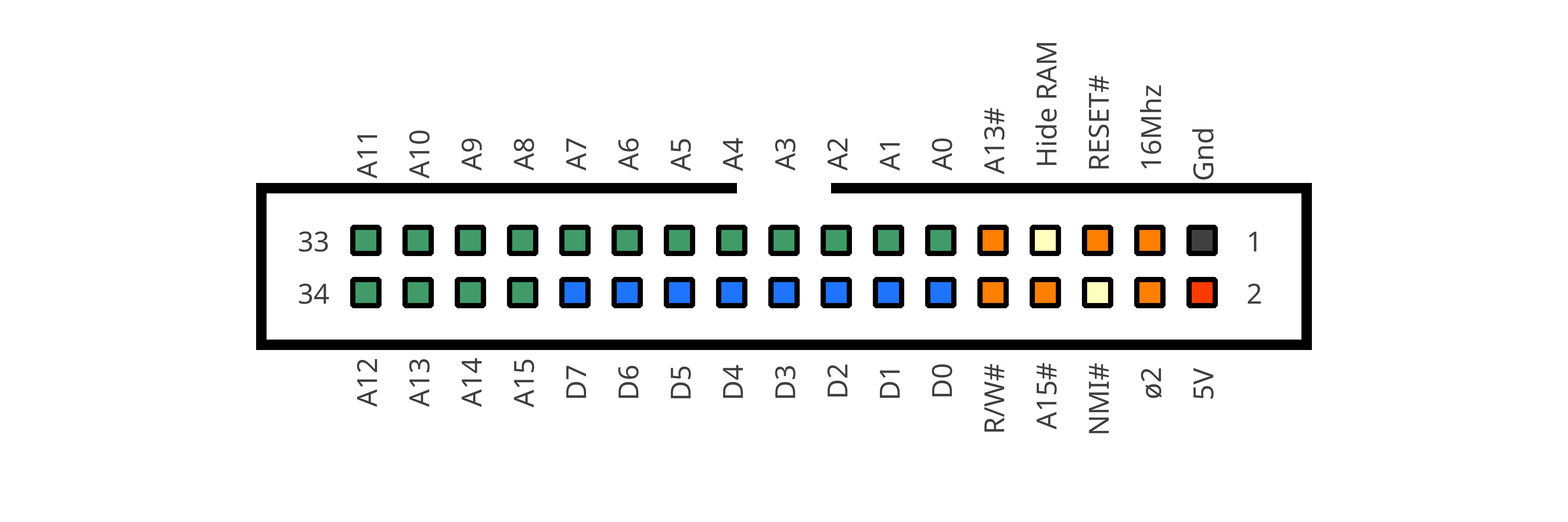
An 8KiB region is set aside in the memory map for expansion roms ($C000-$DFFF), the emulator implements a simple banked rom cartridge where the current bank can be switched by reading from $A0xx, where xx is the bank number, the selected bank is also automatically set to zero on reset.
The bios will automatically jump to address $C008 on boot if it detects an expansion rom that begins with the sring CART-RUN.
Currently expansion roms can be loaded by dragging and dropping a file into the emulator window.
The design uses only 12 integrated circuits:
65c02 - 8bit CPU62256 - 32KiB SRAM39SF010 or 28C64 or 27C256 - 8KiB Program ROM74hc10 - Tripple 3inNAND74hc14 - Hex inverter74hc32 - Quad 2inOR74hc166 - 8bit parallel-to-serial shift register74hc174 - 6bit d-type latch74hc541 - 8bit buffer74hc590*2 - 8bit Counters74hc4520- Dual 4bit CountersThe 8k bios provides a simple command line operating system with the following commands:
| Command | Description |
|---|---|
help | Lists all available commands |
clear | Clears the display |
file | The Size and Name of the currently loaded file |
new | Create a new file |
name <name> | Rename the current file |
edit | Open the file editor |
save | Save file to tape |
load | Load file from tape |
run | Run Loaded File |
peek <addr> <bytes> | Read contents of Memory |
poke <addr> <bytes> | Write to Memory |
prun <addr> | Run a Machine Code Subroutine |
More info on the bios can be found here
| Qty | Value | Footprint | References |
|---|---|---|---|
| 37 | 1N4148 | PCM_Diode_THT_AKL_Double:D_DO-35_SOD27_P7.62mm_Horizontal | D1, D10, D11, D12, D13, D14, D15, D16, D17, D18, D19, D20, D21, D22, D23, D24 +21 |
| 13 | 100nF | PCM_Capacitor_THT_AKL_Double:C_Disc_D3.0mm_W1.6mm_P2.50mm | C4, C5, C6, C7, C8, C9, C10, C11, C12, C13, C14, C15, C17 |
| 4 | MountingHole_Pad | MountingHole:MountingHole_2.2mm_M2_ISO7380_Pad | H1, H2, H3, H4 |
| 3 | 1N4148 | Diode_THT:D_DO-34_SOD68_P2.54mm_Vertical_KathodeUp | D2, D3, D4 |
| 3 | 27KΩ | PCM_Resistor_THT_AKL_Double:R_Axial_DIN0204_L3.6mm_D1.6mm_P7.62mm_Horizontal | R3, R4, R6 |
| 2 | 120Ω | PCM_Resistor_THT_AKL_Double:R_Axial_DIN0204_L3.6mm_D1.6mm_P7.62mm_Horizontal | R7, R8 |
| 2 | 74HC590A | Package_DIP:DIP-16_W7.62mm_LongPads | U1, U2 |
| 2 | DE9_Plug | Smal:DSUB9-Atari | J7, J8 |
| 2 | R_Network04 | Resistor_THT:R_Array_SIP5 | RN2, RN3 |
| 1 | 10µF | PCM_Capacitor_THT_AKL:CP_Radial_D5.0mm_P2.00mm | C16 |
| 1 | 16Mhz | PCM_Crystal_AKL_Double:Crystal_HC49-4H_Vertical | Y1 |
| 1 | 1MΩ | PCM_Resistor_THT_AKL_Double:R_Axial_DIN0204_L3.6mm_D1.6mm_P7.62mm_Horizontal | R2 |
| 1 | 22pF | PCM_Capacitor_THT_AKL_Double:C_Disc_D3.0mm_W1.6mm_P2.50mm | C1 |
| 1 | 27pF | PCM_Capacitor_THT_AKL_Double:C_Disc_D3.0mm_W1.6mm_P2.50mm | C2 |
| 1 | 330Ω | PCM_Resistor_THT_AKL_Double:R_Axial_DIN0204_L3.6mm_D1.6mm_P7.62mm_Horizontal | R1 |
| 1 | 4.7µF | PCM_Capacitor_THT_AKL:CP_Radial_D4.0mm_P1.50mm | C3 |
| 1 | 5.6KΩ | PCM_Resistor_THT_AKL_Double:R_Axial_DIN0204_L3.6mm_D1.6mm_P7.62mm_Horizontal | R5 |
| 1 | 62256 | Package_DIP:DIP-28_W15.24mm_LongPads | U3 |
| 1 | 74HC10 | Package_DIP:DIP-14_W7.62mm_LongPads | U9 |
| 1 | 74HC14 | Package_DIP:DIP-14_W7.62mm_LongPads | U8 |
| 1 | 74HC166 | Package_DIP:DIP-16_W7.62mm_LongPads | U7 |
| 1 | 74HC174 | Package_DIP:DIP-16_W7.62mm_LongPads | U11 |
| 1 | 74HC32 | Package_DIP:DIP-14_W7.62mm_LongPads | U10 |
| 1 | 74HC4520 | Package_DIP:DIP-16_W7.62mm_LongPads | U12 |
| 1 | 74HCT540 | Package_DIP:DIP-20_W7.62mm_LongPads | U6 |
| 1 | A | Smal:SW_Redragon_MX_LowProfile_PCB_1.00u_Other | SW11 |
| 1 | ALT | Smal:SW_Redragon_MX_LowProfile_PCB_1.00u_Other | SW30 |
| 1 | AudioJack4 | Smal:Jack_3.5mm_PJ320A_Horizontal | J3 |
| 1 | B | Smal:SW_Redragon_MX_LowProfile_PCB_1.00u_Other | SW26 |
| 1 | Barrel Jack | Connector_BarrelJack:BarrelJack_GCT_DCJ200-10-A_Horizontal | J6 |
| 1 | Buzzer | Buzzer_Beeper:MagneticBuzzer_Kingstate_KCG0601 | BZ1 |
| 1 | C | Smal:SW_Redragon_MX_LowProfile_PCB_1.00u_Other | SW24 |
| 1 | Conn_02x03_Odd_Even | Connector_PinHeader_2.54mm:PinHeader_2x03_P2.54mm_Vertical | J1 |
| 1 | Conn_02x17_Odd_Even | Connector_IDC:IDC-Header_2x17_P2.54mm_Horizontal | J4 |
| 1 | D | Smal:SW_Redragon_MX_LowProfile_PCB_1.00u_Other | SW13 |
| 1 | E | Smal:SW_Redragon_MX_LowProfile_PCB_1.00u_Other | SW3 |
| 1 | ENT | Smal:SW_Redragon_MX_LowProfile_PCB_1.00u_Other | SW20 |
| 1 | F | Smal:SW_Redragon_MX_LowProfile_PCB_1.00u_Other | SW14 |
| 1 | G | Smal:SW_Redragon_MX_LowProfile_PCB_1.00u_Other | SW15 |
| 1 | H | Smal:SW_Redragon_MX_LowProfile_PCB_1.00u_Other | SW16 |
| 1 | I | Smal:SW_Redragon_MX_LowProfile_PCB_1.00u_Other | SW8 |
| 1 | J | Smal:SW_Redragon_MX_LowProfile_PCB_1.00u_Other | SW17 |
| 1 | K | Smal:SW_Redragon_MX_LowProfile_PCB_1.00u_Other | SW18 |
| 1 | L | Smal:SW_Redragon_MX_LowProfile_PCB_1.00u_Other | SW19 |
| 1 | LED | PCM_LED_THT_AKL:LED_Indicator_D3.0mm_W4.6mm_L6.5mm | D41 |
| 1 | M | Smal:SW_Redragon_MX_LowProfile_PCB_1.00u_Other | SW28 |
| 1 | N | Smal:SW_Redragon_MX_LowProfile_PCB_1.00u_Other | SW27 |
| 1 | O | Smal:SW_Redragon_MX_LowProfile_PCB_1.00u_Other | SW9 |
| 1 | P | Smal:SW_Redragon_MX_LowProfile_PCB_1.00u_Other | SW10 |
| 1 | Q | Smal:SW_Redragon_MX_LowProfile_PCB_1.00u_Other | SW1 |
| 1 | R | Smal:SW_Redragon_MX_LowProfile_PCB_1.00u_Other | SW4 |
| 1 | R_Network06 | Resistor_THT:R_Array_SIP7 | RN1 |
| 1 | S | Smal:SW_Redragon_MX_LowProfile_PCB_1.00u_Other | SW12 |
| 1 | SHIFT | Smal:SW_Redragon_MX_LowProfile_PCB_1.00u_Other | SW21 |
| 1 | SPACE | Smal:SW_Redragon_MX_LowProfile_PCB_1.00u_Other | SW29 |
| 1 | SST39SF0x0 | Package_DIP:DIP-32_W15.24mm_LongPads | U4 |
| 1 | SW_Push | Button_Switch_THT:SW_Tactile_SKHH_Angled | SW31 |
| 1 | SW_SPDT | Button_Switch_THT:SW_Slide_SPDT_Angled_CK_OS102011MA1Q | SW32 |
| 1 | T | Smal:SW_Redragon_MX_LowProfile_PCB_1.00u_Other | SW5 |
| 1 | U | Smal:SW_Redragon_MX_LowProfile_PCB_1.00u_Other | SW7 |
| 1 | V | Smal:SW_Redragon_MX_LowProfile_PCB_1.00u_Other | SW25 |
| 1 | VGA | Connector_Dsub:DSUB-15-HD_Female_Horizontal_P2.29x1.98mm_EdgePinOffset3.03mm_Housed_MountingHolesOffset4.94mm | J2 |
| 1 | W | Smal:SW_Redragon_MX_LowProfile_PCB_1.00u_Other | SW2 |
| 1 | W65C02SxP | Package_DIP:DIP-40_W15.24mm | U5 |
| 1 | X | Smal:SW_Redragon_MX_LowProfile_PCB_1.00u_Other | SW23 |
| 1 | Y | Smal:SW_Redragon_MX_LowProfile_PCB_1.00u_Other | SW6 |
| 1 | Z | Smal:SW_Redragon_MX_LowProfile_PCB_1.00u_Other | SW22 |


KITTY-6502/hardware
the KITTY is a 65c02 homebrew kit microcomputer designed around text mode graphics and cartridge media. It is fully open source, and uses exclusively in-production parts.


nicolacimmino/PLC-14500
Retro trainer board based on the MC14500 1-bit ICU. The project is OSHW certified and a ready to assemble kit is available on Tindie.
It measures 190 × 100 mm and has 2 copper layers, 1.6 mm thick.
126 parts, built around the 74HCT540D, 74HC590ADW, 74HC10D and 74HC14. The full list of its parts is on this page, with links to each part's symbol and footprint where PCBKit's library has them.
From the smaldragon/MicroMicro repository on GitHub, at the commit this page was made from: the board is Kicad/a1/a1.kicad_pcb and its schematic Kicad/a0/a0.kicad_sch. PCBKit opens the board in the browser, with nothing to install.
Its repository publishes it under the Unlicense licence: you may reuse it on that licence's terms (keep the author's notice, and for a copyleft licence share your changes alike).