6 layers90 × 90 mm
Codex micro wired revA route nognd
slopus/codex-keybored
A 100% vibe-coded hardware build: Fusion 360, six-layer KiCad PCB, STM32 firmware, and live JLC factory handoff.
97 parts10

 slopus/codex-keybored10
A 100% vibe-coded hardware build: Fusion 360, six-layer KiCad PCB, STM32 firmware, and live JLC factory handoff.
Codex micro wired revA is an open-source printed circuit board by slopus, from the slopus/codex-keybored repository on GitHub. It is a 6-layer board of 90 × 90 mm with 85 parts on 66 nets, routed with 790 tracks and 102 vias.
It is built around the STM32F072CBT6, TTP223-BA6-TD and ME6211C33M5G-N, with the SN74AHCT1G125DBVR(UMW), USBLC6-2SC6 and SK6812MINI-E among its other parts. Its parts include 36 diodes, 14 switches, 11 capacitors, 5 ICs and 4 resistors. It belongs with the robots and motor control and keyboards and input boards and the STM32 boards of this library.


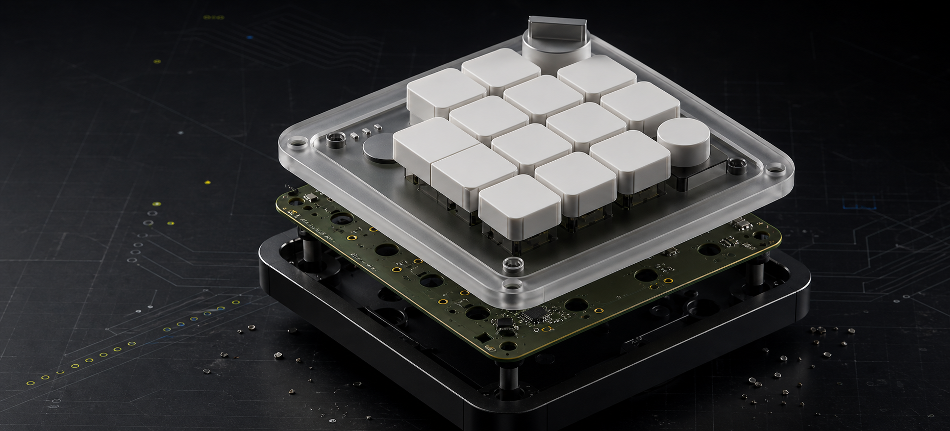
A from-scratch, manufacturable parody of the Codex Micro: Fusion 360 mechanics,
four quoted CNC parts, a wired six-layer PCB, turnkey assembly instructions, and working USB HID firmware.
VIEW THE MANUFACTURING DOSSIER · DOWNLOAD COMPLETE HANDOFF · OPEN FUSION ARCHIVE




THE DELIGHTFUL PART IS THAT THE VIBE DID NOT STOP WHEN THE WORK BECAME PHYSICAL.
It crossed industrial design, parametric CAD, CNC drawings, multilayer electronics, component sourcing,
USB firmware, factory testing, pricing, and vendor handoff. Every layer is editable, inspectable, and ready to continue.
Most vibe-coded projects end at a screenshot. This one kept going until the pixels became toleranced solids, the solids became quoted CNC parts, the control layout became a routed six-layer PCB, the PCB became Gerbers/BOM/CPL, the firmware became checksummed factory binaries, and the whole stack became live JLC manufacturing jobs.
That is the fun of this repository: the same conversational build loop moves through every engineering discipline without hiding the seams. “The aluminum base is slightly tilted” became a 5° Fusion body. “Not a foot, a ring” became a purchased JIS G‑65 O-ring, a concentric retention groove, refreshed STEP/DXF/PDF exports, a successful JLCCNC import, a $68.31 live base quote, and a cleaned cart. “I do not want to solder switches” became a both-side PCBA configuration, consigned-parts manifest, 74-position placement file, manual assembly contract, flashing procedure, and functional acceptance test.
| Vibe-coding pass | What was created | Where it became real |
|---|---|---|
| Look closely | Public renders were compared, scaled, and converted into an explicit confirmed/measured/inferred datum set | Research notes + manufacturing dossier |
| Make it solid | A parametric 108 × 108 mm assembly, corrected wedge, captured light pipe, joystick cap, and purchased continuous grip ring | Fusion 360 scripts + four STEP/DXF packages + G‑65 vendor reference |
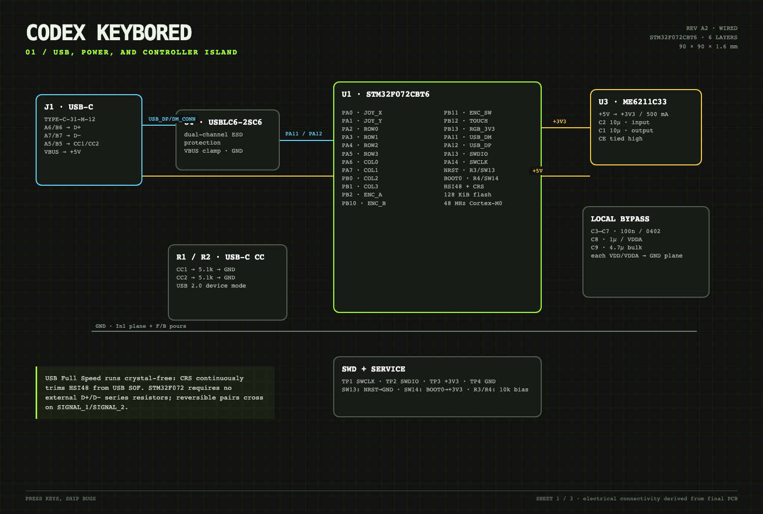
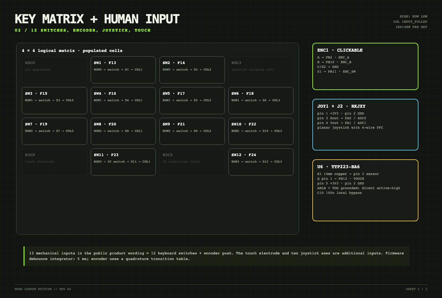
| Make it electronic | A clean-room STM32F072 architecture, matrix, USB-C, touch, joystick, 24 RGB pixels, six copper layers | KiCad source + 0-error DRC + IPC netlist |
| Make it behave | USB HID firmware, neutral F13–F24 map, RGB safety limit, factory browser test | BIN/HEX/ELF + SHA-256 checksums |
| Make it buildable | LCSC mappings, BOM/CPL, specialty-parts sourcing, manual operations, inspection gates | Turnkey factory ZIP + controlled SOP |
| Make the factory answer | CAD and fabrication files were uploaded into authenticated quote flows | Four current JLCCNC items + JLCMC G‑65 ring + JLCPCB job Y5 |
PROMPT → RESEARCH → DIMENSIONS → FUSION 360 → STEP/DXF → JLCCNC
                     ↓
              ELECTRICAL PLAN → KICAD → GERBER/BOM/CPL → JLCPCB
                     ↓
              FIRMWARE → FACTORY TEST → TURNKEY HANDOFF → A FEW FINAL SCREWS
The result is not “AI made a picture of a keyboard.” The result is a versioned hardware project in which a vibe-driven decision can be traced from sentence to parameter, from parameter to geometry or net, and from production file to a factory price. That end-to-end continuity is the project.
| Mechanical | Electronics | Factory route |
|---|---|---|
| 108 × 108 mm outer envelope | 90 × 90 mm, six copper layers | 4 CNC parts already quoted |
| 5° machined aluminum wedge | STM32F072 + USB-C + TinyUSB | 5 PCBs / 2 PCBA in turnkey job Y5 |
| Parametric Fusion assembly + STEP/DXF | 12 keys + encoder + touch + joystick | Specialty parts consigned to the factory |
| Black POM, clear PMMA, 6061-T6, NBR | 24 reverse-mount RGB pixels | Flash, functional test, and evidence in SOP |
| Controlled drawing pack | 0 DRC violations / 0 unconnected nets | Customer closes only a few enclosure screws |
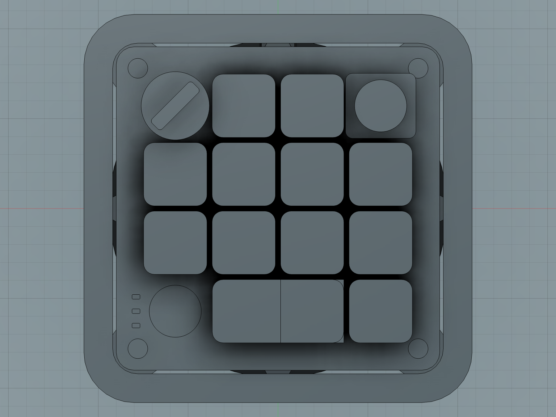 FUSION 360 / TOP — measured mechanical interface | 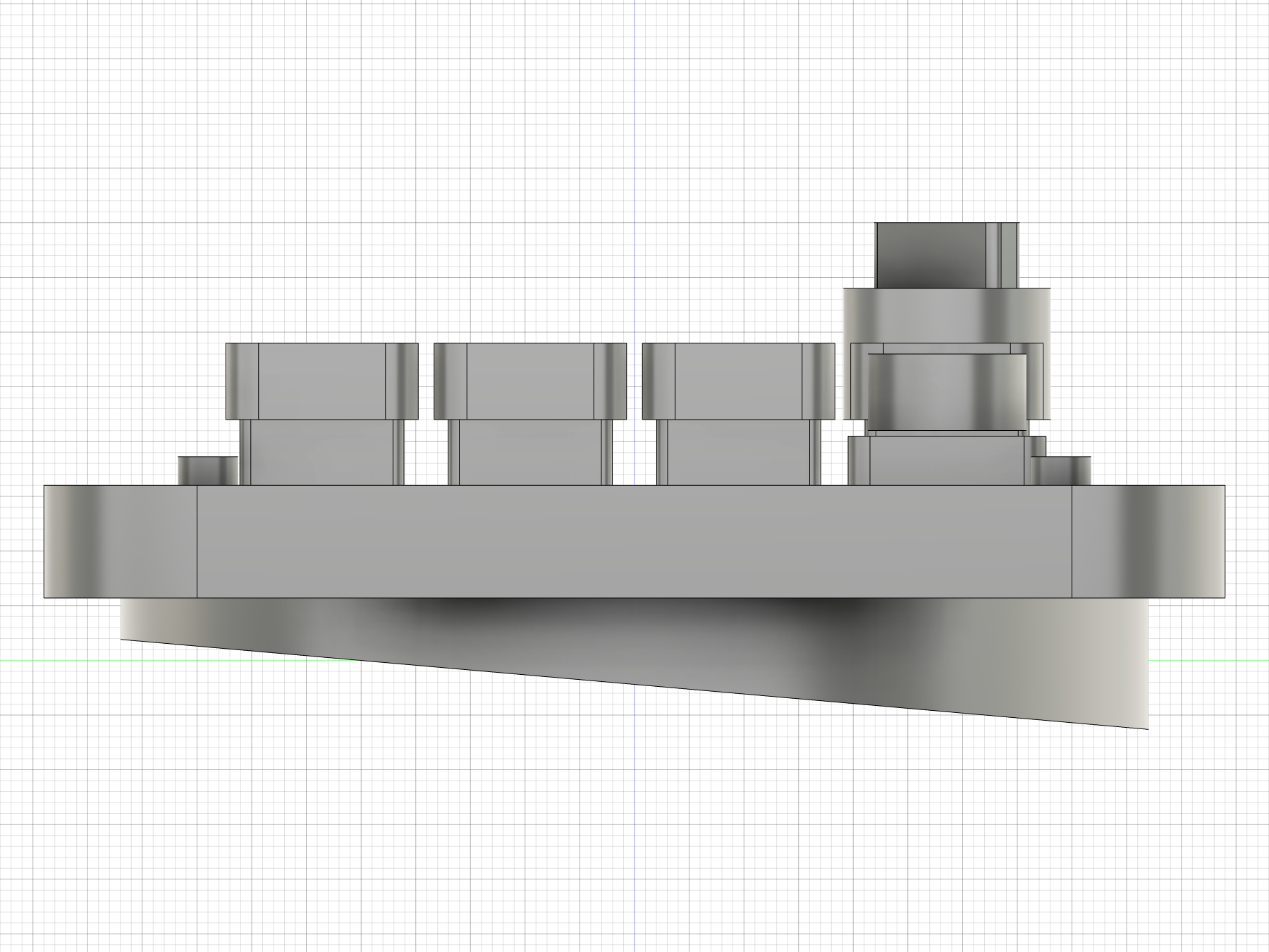 FUSION 360 / SIDE — corrected 5° wedge |
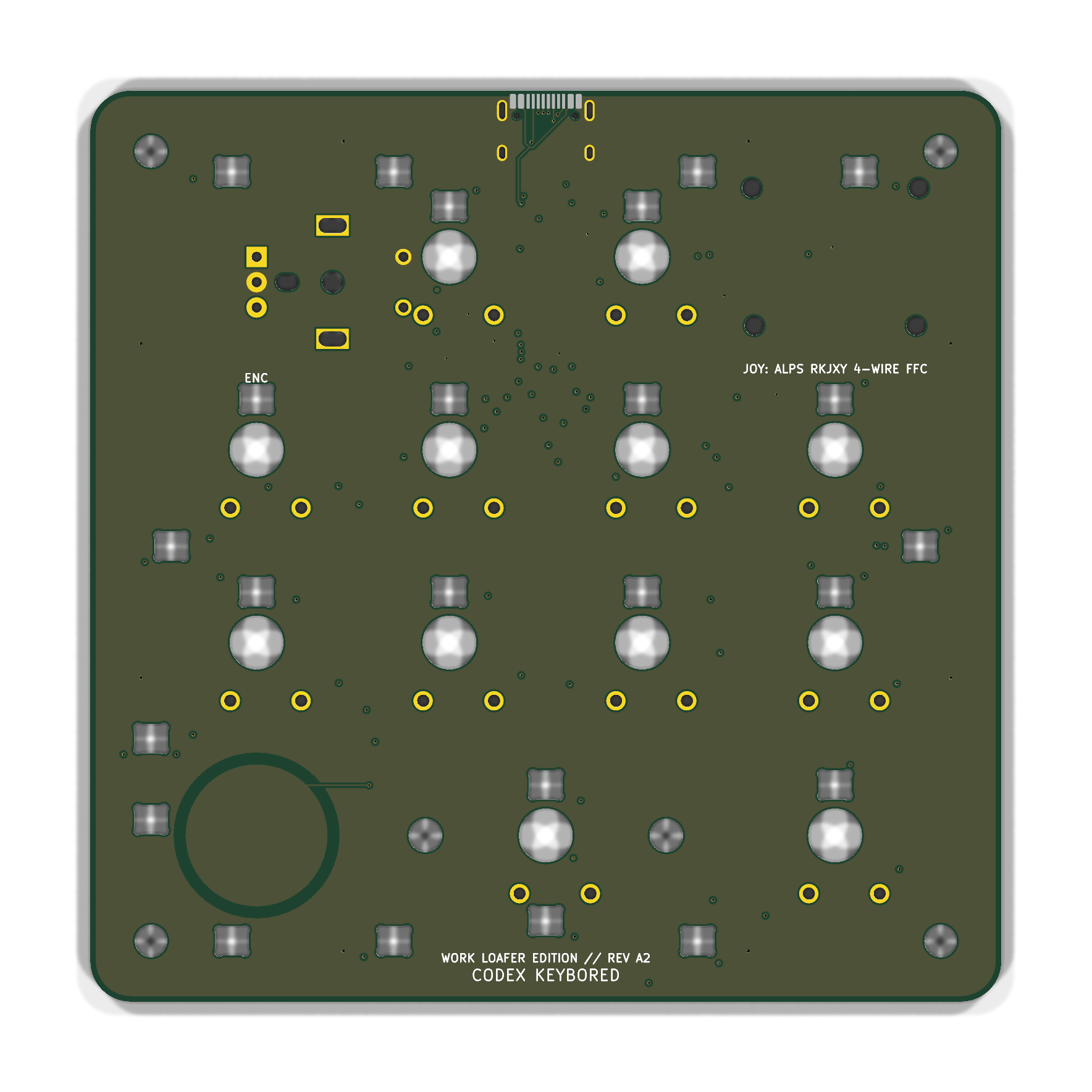 PCB / TOP — WORK LOAFER EDITION silk | 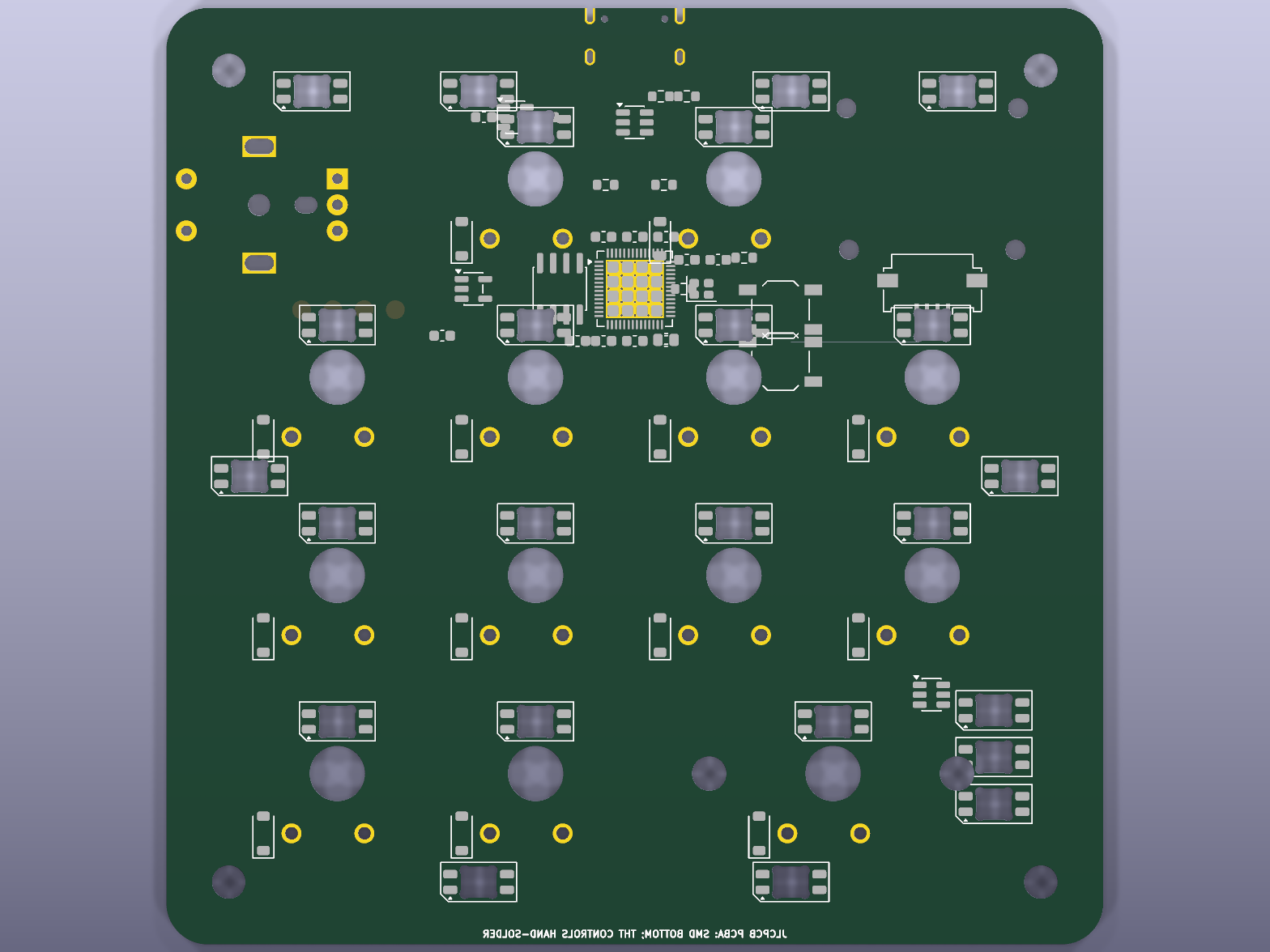 PCB / BOTTOM — controller island, power, matrix, RGB |
ZERO SOLDERING AT HOME. The production route asks JLC to place both-side SMD, manually install the twelve switches and encoder, fit the joystick/FFC, flash the STM32, exercise all 20 USB HID events, inspect all 24 RGB emitters, and install the caps on the primary unit. The customer-facing operation is enclosure closure after first-article approval.
The automatic JLC matcher uses the catalog-only BOM and CPL. The complete manual/secondary-operation contract is in the turnkey SOP, expanded BOM, 74-position CPL, and consigned-parts manifest.
SOURCE SPECIALTY PARTS  →  BOTH-SIDE PCBA  →  MANUAL CONTROLS
→ FLASH + FUNCTION TEST → PHOTO EVIDENCE → ENCLOSURE CLOSUREQuotes were captured in an authenticated JLC session on July 17, 2026. Prices are dynamic and exclude possible tax, duty, and engineering-review additions.
| Job | Configuration | Captured price |
|---|---|---|
| CM2-001 upper housing | CNC polished black POM, qty 1 | $88.97 |
| CM2-002 angled weight | CNC 6061-T6, 5° wedge + G‑65 groove, qty 1 | $68.31 |
| CM2-003 light pipe | CNC clear cast PMMA, polished edges + frosted face, qty 1 | $45.70 |
| CM2-004 joystick cap | CNC POM fit prototype, qty 1 | $19.42 |
| CM2-005 continuous grip ring | JLCMC AMFG-P5-A65-65 / black NBR 65A, qty 1 | $0.16 |
| Mechanical subtotal | Four current CNC parts + purchased ring | $222.56 |
| JLCPCB turnkey base | Five PCBs + two both-side Standard PCBA | $193.01 |
| Captured manufacturing floor | Mechanical merchandise + PCBA base, before manual review, special parts, tax/duty/shipping | $415.57 |
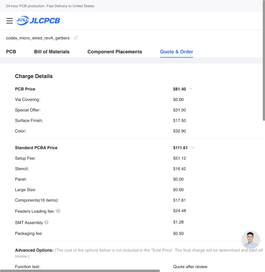
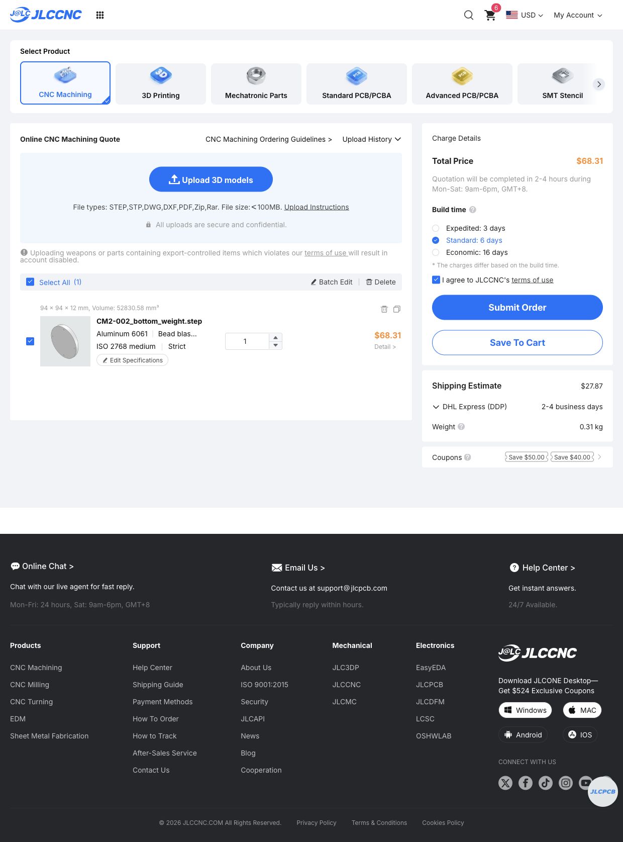
The $193.01 PCB/PCBA figure is a captured base, not a promise of a finished-device total. Programming, functional test, secondary manual operations, and consigned-part handling remain quote-after-review. The saved cart proves that the geometry and six-layer board can enter the vendor workflow; JLC engineering approval is still the gate before payment.
| Area | Source of truth | Ready-to-send artifact |
|---|---|---|
| Fusion mechanics | fusion/build_codex_micro_mechanical.py | Codex_Micro_RevA.f3d |
| CNC geometry | Fusion BRep bodies | cnc/STEP/ + cnc/DXF/ |
| CNC dimensions | Parametric model + controlled notes | CM2_CNC_Drawing_Pack_RevB.pdf |
| PCB connectivity/layout | codex_micro_wired_revA.kicad_pcb | Gerber/drill ZIP |
| Assembly data | Board-derived generator | JLC BOM + JLC CPL |
| Principle schematic | Final routed connectivity | Three-sheet PDF + IPC-D-356 |
| Firmware | firmware/stm32/ | BIN + HEX + checksums |
| Factory contract | Mechanics Rev B + electronics Rev A2 | Complete order handoff ZIP + mechanical factory ZIP |
| Full report | Evidence, screenshots, prices, sources | Single-page dossier + Rev B PDF |
F.Cu, GND plane, two signal layers, +5V plane, B.Cu.
The coordinate origin is the device center. +Y points toward the rear edge; +Z points upward.
| Parameter | Value | Confidence | Basis |
|---|---|---|---|
| Key pitch | 19.05 mm | CONFIRMED | Work Louder MX keycap specification |
| Installed keyboard switches | 12 | CONFIRMED | Visible layout + Creator Micro 2 specification |
| Total mechanical switch inputs | 13 | CONFIRMED | Includes encoder push |
| Outer envelope | 108 × 108 mm | MEASURED | Official top render scaled from key centers |
| Top PCB/panel | 90 × 90 × 1.6 mm | MEASURED / INFERRED | Render scale + standard PCB thickness |
| PCB screw pitch | 78 × 78 mm | MEASURED | Provisional ±0.5 mm |
| Upper housing | 108 × 108 × 10.3 mm, R14 | MEASURED | Public front/side/top renders |
| Aluminum bottom | Ø94 mm, 3.8→12.0 mm, 5° | MEASURED / INFERRED | Side profile + CNC construction |
| G‑65 retention groove | Ø67.5 mm centerline × 3.6 W × 2.2 D | ENGINEERED | G‑65 section, screw clearance, 1.6 mm minimum Al floor |
| Continuous grip ring | JIS B 2401 G‑65, ID 64.4, section 3.1, OD 70.6 mm | PURCHASED / VERIFIED | JLCMC AMFG-P5-A65-65 |
| Joystick candidate | Alps RKJXY1000006 | CANDIDATE | Available electrical/mechanical sibling |
Confidence language is deliberate:
The current quoted Rev B build uses polished black POM for the upper housing and joystick cap, black-anodized 6061-T6 for the 5° base, clear cast PMMA for the captured light pipe, and a purchased black NBR G‑65 ring. A wood upper remains a future material experiment, but it is not the current cart configuration.
All four STEP files passed JLC's automated CNC import. The current bottom was explicitly corrected from an early flat disc to the observed 5° wedge, then revised again with the G‑65 retention groove before the $68.31 configuration was saved. Obsolete flat/no-groove parts and individual rubber feet were removed from the cart.
Codex, then run fusion/build_codex_micro_mechanical.py.fusion/ and compare them with the controlled drawing pack.firmware/stm32/ or use the checksummed release image.This is an independent private prototype, reconstructed from official public product renders and published platform/component documentation. It is not an official OpenAI or Work Louder CAD/electronics release, is not affiliated with or endorsed by either company, and contains no leaked manufacturing data.
The digital production gate is clean: Gerbers, drill files, BOM/CPL, IPC netlist, three-sheet principle schematic, firmware, STEP/DXF, drawings, and vendor quote evidence are present. The physical gate is still open: no fabricated Rev A2 board has completed electrical bring-up, EMC evaluation, or dimensional fit-check. Use a current-limited supply, verify the 3.3 V rail and SWD first, and treat the first order as an engineering prototype.
Primary research links and detailed source notes live in the manufacturing dossier and firmware-and-compliance-notes.md.
CODEX KEYBORED / WORK LOAFER EDITION / MECHANICS REV B + ELECTRONICS REV A2
| Qty | Value | Footprint | References |
|---|---|---|---|
| 24 | SK6812MINI-E | LED_SK6812MINI-E_3.2x2.8mm_P1.5mm_ReverseMount | LED1, LED2, LED10, LED11, LED12, LED13, LED14, LED15, LED16, LED17, LED18, LED19, LED20, LED21, LED22, LED23 +8 |
| 12 | 1N4148W | D_SOD-123 | D1, D2, D3, D4, D5, D6, D7, D8, D9, D10, D11, D12 |
| 12 | Gateron_KS-33_H10B050NN-Y24 | SW1, SW2, SW3, SW4, SW5, SW6, SW7, SW8, SW9, SW10, SW11, SW12 | |
| 6 | MountingHole_M3 | H1, H2, H3, H4, HSTAB1, HSTAB2 | |
| 5 | 100nF_3V3 | C_0402_1005Metric | C3, C4, C5, C6, C7 |
| 2 | 10uF | C_0603_1608Metric | C1, C2 |
| 1 | 100nF_TOUCH | C_0603_1608Metric | C10 |
| 1 | 10k_BOOT0_PULLDOWN | R_0603_1608Metric | R4 |
| 1 | 10k_NRST_PULLUP | R_0603_1608Metric | R3 |
| 1 | 1uF_VDDA | C_0402_1005Metric | C8 |
| 1 | 3V3 | TP3 | |
| 1 | 4.7uF_3V3_BULK | C_0603_1608Metric | C9 |
| 1 | 5.1k_CC1 | R_0603_1608Metric | R1 |
| 1 | 5.1k_CC2 | R_0603_1608Metric | R2 |
| 1 | Alps_RKJXY100000A_MECHANICAL | JOY1 | |
| 1 | BOOT | SW_SPST_TL3342 | SW14 |
| 1 | CAP_TOUCH_14MM | E1 | |
| 1 | CL32A107MQVNNNE_100uF_6V3 | C_1210_3225Metric | C19 |
| 1 | EC11E_VERTICAL_CLICK | RotaryEncoder_Alps_EC11E-Switch_Vertical_H20mm_MountingHoles | ENC1 |
| 1 | GND | TP4 | |
| 1 | ME6211C33M5G | SOT-23-5 | U3 |
| 1 | RESET | SW_SPST_TL3342 | SW13 |
| 1 | RKJXY_4WIRE_FFC | Molex_200528-0040_1x04-1MP_P1.00mm_Horizontal | J2 |
| 1 | SN74AHCT1G125DBVR | SOT-23-5 | U5 |
| 1 | STM32F072CBT6 | LQFP-48_7x7mm_P0.5mm | U1 |
| 1 | SWCLK | TP1 | |
| 1 | SWD | TP2 | |
| 1 | TTP223-BA6-TD | SOT-23-6 | U6 |
| 1 | USBLC6-2SC6 | SOT-23-6 | U4 |
| 1 | USB_C_HRO_TYPE-C-31-M-12 | USB_C_Receptacle_HRO_TYPE-C-31-M-12 | J1 |
slopus/codex-keybored
A 100% vibe-coded hardware build: Fusion 360, six-layer KiCad PCB, STM32 firmware, and live JLC factory handoff.

picafe/bicolor-matrix-v2
A 32x8 bicolor LED matrix module composed of 4 8x8 matrices based on the Holtek HT16K33A I2C LED driver. V1 paired it with a stacked adapter (RP2040 Zero + DS3231 module); V2 redesigns the matrix routing and puts an…


hdh7485/agent-deck
Physical AI agent controller for Codex, Hermes, OMX, and tmux workflows

sporkus/le_chiffre_keyboard_stm32
Le Chiffre keyboard pcb with stm32F072

MohamedAlDeep/RGB-Mechanical-KEEB-
This is my custom made 75% rgb mechanical keyboard

xommmmmmmm/superposition-borked
A Planck drop-in solder/Mill-Max PCB for Choc v2 and KS-33, with Ortho/Alpha Stagger and various bottom rows.

h3ll5ur7er/TokenBoard
You wouldn't vibe code a keyboard.. or would you? uses konnect to interact with KiCad and CADence to model the case

andrewsharmon/rp2350-stepper-controller
Low-cost 10-axis sine-microstepping controller for small steppers on the RP2350 (PIO + DMA). WIP.
It measures 90 × 90 mm and has 6 copper layers, 1.6 mm thick.
85 parts, built around the STM32F072CBT6, TTP223-BA6-TD, ME6211C33M5G-N and SN74AHCT1G125DBVR(UMW). The full list of its parts is on this page, with links to each part's symbol and footprint where PCBKit's library has them.
From the slopus/codex-keybored repository on GitHub, at the commit this page was made from: the board is electronics/kicad/codex_micro_wired_revA.kicad_pcb. PCBKit opens the board in the browser, with nothing to install.
Its repository states no licence, so its author keeps all rights: ask slopus before reusing the design.