2 layers77 × 41.7 mm
BluetoothPedal Server
skngh/RidgeField
Bluetooth guitar pedal using the Daisy Seed. Sends controls from a guitar mounted box to the enclosure on your pedalboard.
26 parts9MIT

 skngh/RidgeField9
Bluetooth guitar pedal using the Daisy Seed. Sends controls from a guitar mounted box to the enclosure on your pedalboard.
BluetoothPedal Main is an open-source printed circuit board by skngh, from the skngh/RidgeField repository on GitHub, published under the MIT licence. It is a 2-layer board of 52 × 59 mm with 40 parts on 72 nets, routed with 153 tracks and 24 vias.
It is built around the TL072CDR-CN, TPS62163DSGT and CC0805KKX7R8BB105, with the CC0805MKX5R8BB226, CC0805JRNPO9BN101 and CC0805KKX5R8BB106 among its other parts. Its parts include 12 capacitors, 10 resistors, 3 ICs, 3 diodes and 3 connectors. It belongs with the audio and music and radio and wireless boards and the ESP32 and RISC-V boards of this library.


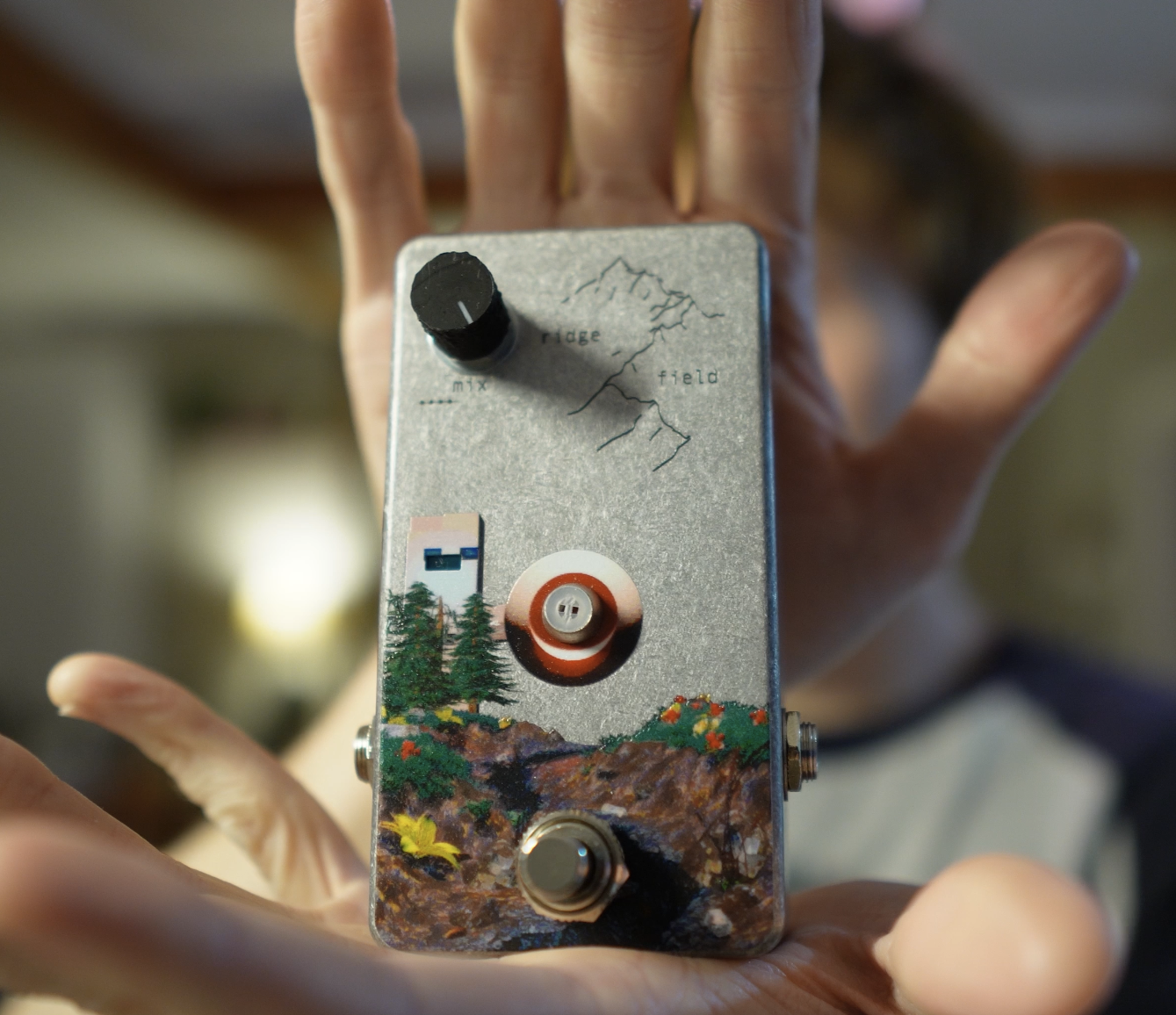
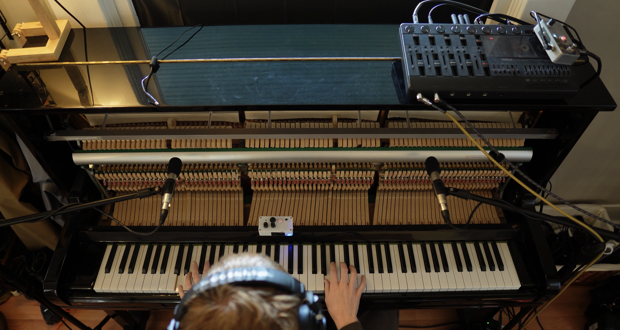
Fully wireless guitar pedal. A small box mounts on the guitar and sends its knobs, joystick and light sensor over Bluetooth to the pedal on the floor, which runs everything and does processing through a Daisy Seed.
Full video walking through the pedal!
Everything here is free to use!! Please let me know if you make anything with something here, I'd really love to see :)
hardware/: KiCad projects for both boards, fabrication files that are ready to order, and parts list for non pre-assembled partsfirmware/: all the code
firmware/daisy/: the audio DSP running on the Daisy Seed in the pedalfirmware/ESP32C3/: the Bluetooth link (guitar-side server and pedal-side client)enclosure/: FreeCAD models, STLs, and the Tayda drill templateThere are two units:
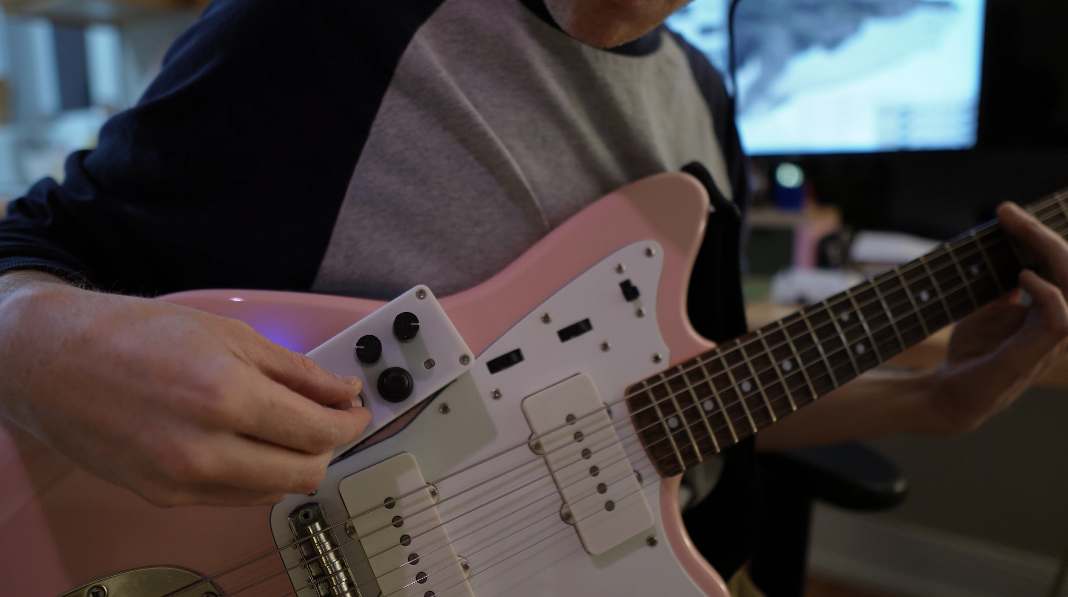
| Control | What it does |
|---|---|
| Knob 1 | Delay time |
| Knob 2 | Delay feedback (fully down turns the delay off) |
| LDR | Reverb. Cover it with your hand for more |
| Joystick X | Pitch shift, an octave up or down depending on direction |
| Joystick Y | Bitcrusher. One direction lowers bit depth, the other lowers sample rate |
| Button press | Latch the current joystick position |
| Button hold | LDR calibration, see below |
| Mix knob (pedal) | Dry/wet |
| Footswitch (pedal) | Bypass |
LDR calibration: hold the joystick button. For the first few seconds leave the LDR uncovered. Once the LED starts blinking fast, cover it and keep holding until the LED goes back to normal (~7 s total). The pedal saves the calibration so it survives next time you unplug and replug.
Rough order:
hardware/PCBWayFiles (Gerbers, BOM and pick-and-place are all there).hardware/PARTS.mdenclosure/STL files. Uses M3x6mm screws and M3 heat inserts.firmware/ESP32C3, then build and flash the Daisy from firmware/daisy.See each folder's README for more details.
I got the art on the enclosure UV printed through Tayda. The art isn't included in this repo, but here's how I did it in Blender!
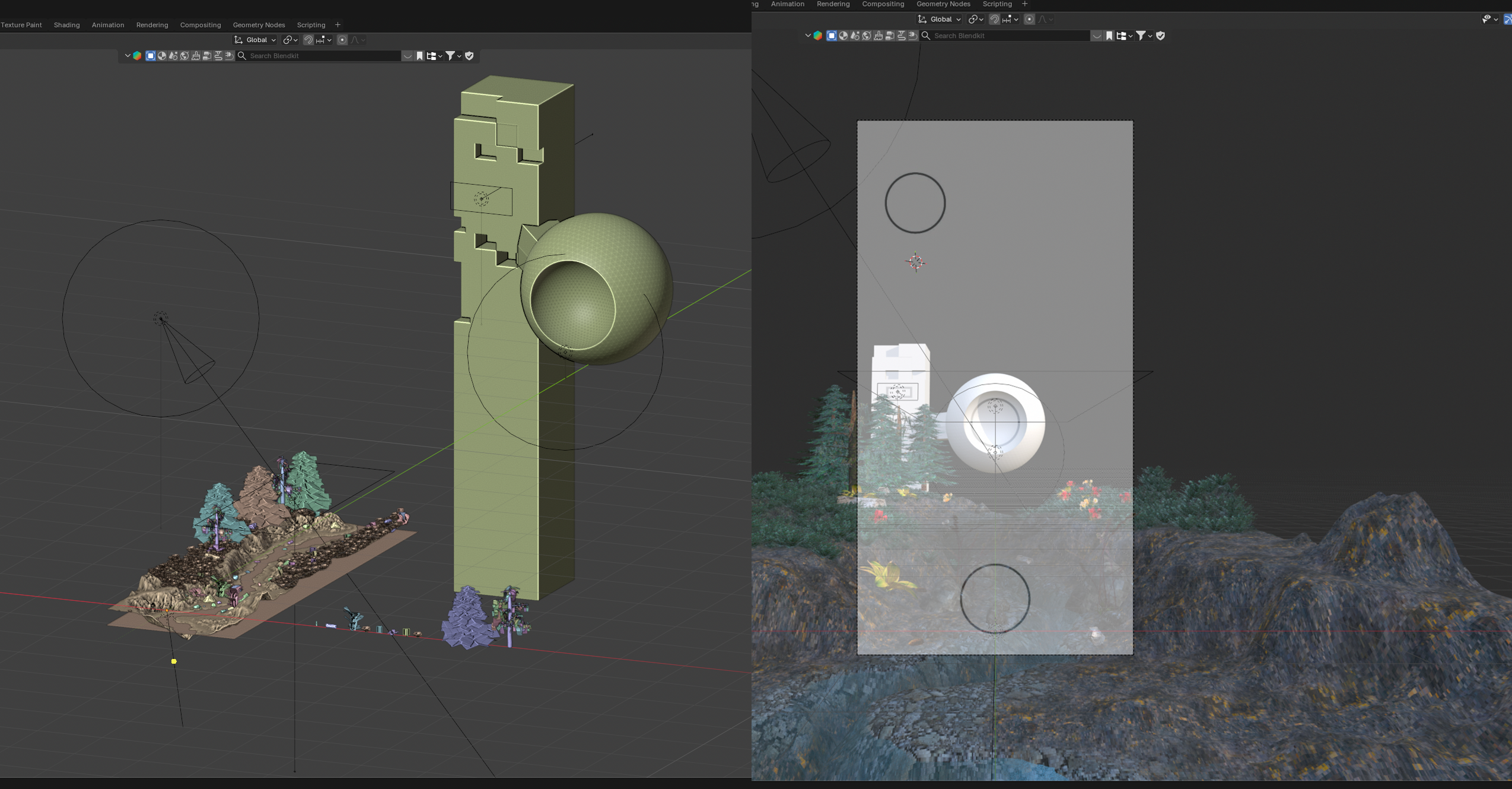
You can attach an image as a background to a camera in Blender. So I took the drill schematic coords and made an illustrator file showing the holes that I added as the background. Then I could easily place objects in the scene and it would line up later with the pedal (for some reason the bluetooth LED on the left didn't line up perfectly, so I think I must've gotten the coords off a tiny bit).
I have a video here showing how to make designs for Tayda's UV printing service.
The DSP library I used is a git submodule, so clone with:
git clone --recursive https://github.com/skngh/RidgeField.git
# if you already cloned it:
git submodule update --initAs I mentioned in the video, I am actually planning on making a V2 of the main pedal PCB going forward. It is fully functioning, but you can hear some of the data transfers as these consistent beeps going, and I'm an idiot who didn't add a LPF to the output buffer, so there's lots of high frequency noise. It's far above the range of human hearing, but I had this issue in the past where some annoying looper pedal folded that range down and caused all this aliasing (at least I think that's what happened), so I plan on making the board 4 layers and then adding a LPF across the output buffer's op amp. Relatively easy, but in order to test I'd have to reorder the boards and I don't really wanna spend that money right now :o
| Qty | Value | Footprint | References |
|---|---|---|---|
| 4 | 1M | Resistor_SMD:R_0805_2012Metric | R2, R3, R4, R5 |
| 4 | TestPoint | TestPoint:TestPoint_Pad_D2.0mm | TP1, TP2, TP3, TP4 |
| 3 | 100n | Capacitor_SMD:C_0805_2012Metric | C7, C11, C12 |
| 3 | 1K | Resistor_SMD:R_0805_2012Metric | R1, R11, R12 |
| 3 | 1u | Capacitor_SMD:C_0805_2012Metric | C3, C4, C5 |
| 3 | 22uF | Capacitor_SMD:C_0805_2012Metric | C6, C8, C10 |
| 2 | 100K | Resistor_SMD:R_0805_2012Metric | R6, R8 |
| 2 | AudioJack2 | Connector_Wire:SolderWire-0.5sqmm_1x02_P4.6mm_D0.9mm_OD2.1mm | J1, J2 |
| 1 | 100R | Resistor_SMD:R_0805_2012Metric | R7 |
| 1 | 100p | Capacitor_SMD:C_0805_2012Metric | C1 |
| 1 | 10uF | Capacitor_SMD:C_0805_2012Metric | C9 |
| 1 | 1n | Capacitor_SMD:C_0805_2012Metric | C2 |
| 1 | 2.2uH | Custom_Footprints:Coilcraft_XFL3012 | L1 |
| 1 | Electrosmith_Daisy_Seed_Rev4 | Module:Electrosmith_Daisy_Seed | A1 |
| 1 | FerriteBead | Inductor_SMD:L_0805_2012Metric | FB1 |
| 1 | LED | LED_THT:LED_D5.0mm | D2 |
| 1 | LED | LED_THT:LED_Rectangular_W5.0mm_H2.0mm | D3 |
| 1 | R_Potentiometer | Custom_Footprints:RV11114NO | RV1 |
| 1 | SS14 | Diode_SMD:D_SMA | D1 |
| 1 | SW_SPST | Connector_Wire:SolderWire-0.5sqmm_1x02_P4.6mm_D0.9mm_OD2.1mm | SW1 |
| 1 | Screw_Terminal_01x02 | PedalParts:Screw Terminal 1x2 5mm | J3 |
| 1 | TL072 | Package_SO:SOIC-8_3.9x4.9mm_P1.27mm | U1 |
| 1 | TPS62163DSGT | Package_SON:WSON-8-1EP_2x2mm_P0.5mm_EP0.9x1.6mm_ThermalVias | U2 |
| 1 | XIAO-ESP32-C3-DIP | Custom_Footprints:XIAO-ESP32-C3-DIP | U3 |
skngh/RidgeField
Bluetooth guitar pedal using the Daisy Seed. Sends controls from a guitar mounted box to the enclosure on your pedalboard.

reparationchlorinateur/gree-bridge
ESP32-S3 board that goes inside a mini-split indoor unit, for Home Assistant and Apple Home (Matter). IR control and wall-remote feedback through the unit's own IR receiver line (most brands); indoor/outdoor bus readout…


doug-harriman/E-Display
Electronic display for calendars, weather, etc.


OrbitalCommons/gumstick
Gumstick: ESP32 + iCE40UP5K FPGA module (v1 DF40 board-to-board, v2 M.2 gold-finger draft) and its programming carrier. KiCad 10.

lolz0r/Williams-WPC-Power-Driver-Board-A-12697-3
Untested, unverifed, AI created design.

barkinvar/sugerCANe
A compact interface for three NPN, PNP or logic sensors on an FRC robot. Each port has a removable 5 V / 12 V power jumper; input type is configured in software.

nunosousa/SCART-switcher
An old school SCART switcher. Its main purpose will be to automaticaly detect and switch the video output to the active input video source.
It measures 52 × 59 mm and has 2 copper layers, 1.6 mm thick.
40 parts, built around the TL072CDR-CN, TPS62163DSGT, CC0805KKX7R8BB105 and CC0805MKX5R8BB226. The full list of its parts is on this page, with links to each part's symbol and footprint where PCBKit's library has them.
From the skngh/RidgeField repository on GitHub, at the commit this page was made from: the board is hardware/BluetoothPedal_Main/BluetoothPedal_Main.kicad_pcb and its schematic hardware/BluetoothPedal_Main/ADC.kicad_sch. PCBKit opens the board in the browser, with nothing to install.
Its repository publishes it under the MIT licence: you may reuse it on that licence's terms (keep the author's notice, and for a copyleft licence share your changes alike).