2 layers
Encoder
byrantech/laptop
anyon_e, a highly integrated, high end, open source laptop. Attempt the impossible.
7 parts4.3kMIT

 skiselev/micro_8088_case53
Case for Micro 8088
Micro 8088 Front Panel is an open-source printed circuit board by skiselev, from the skiselev/micro_8088_case repository on GitHub, published under the GPL-3.0 licence. It is a 2-layer board of 48 × 14 mm with 7 parts on 10 nets, routed with 45 tracks and 0 vias.
Its parts include 2 diodes, 2 switches and 1 connector.
Case for Micro 8088 and ISA 8-Bit Backplane Based Computer
This case is intended to be used with Micro 8088 and ISA 8-Bit Backplane based computer.
The front panel features the standard Intel* 9-pin front panel pinout, and can work with other systems as well.
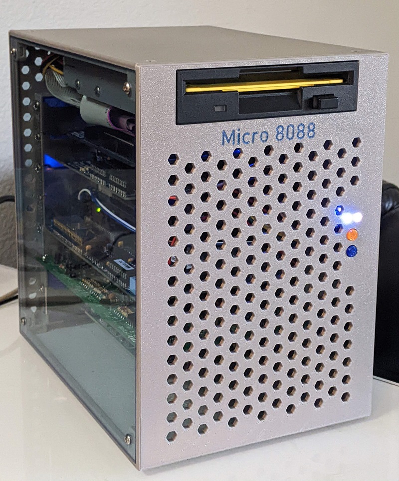
Parts can be printed using PETG or other fillament. The parts are designed to be printed without supports, with the exception of the case back, which needs supports for the DC power connector area.
| Part | File | Notes |
|---|---|---|
| Case Front | case_front.stl | For the system name in colored letters, print sytem_name.stl first |
| Case Back | case_back.stl | |
| Case Bottom | case_bottom.stl | Use supports on the build plate only option when printing |
| Case Top | case_top.stl | It is possible to use a 192.8 mm * 192.8 mm piece of transparent 1/8" / 3 mm acrylic plastic instead |
| Case Left | case_left.stl | |
| Case Right | case_right.stl | |
| ISA Slots Cover | slots_cover.stl | Snaps into the Case Back |
| Speaker Bracket | speaker_bracket.stl | |
| System Name | system_name.stl | System Name "Micro 8088". Print and remove the rectangle on the perimeter. Next print case_front.stl |
| Keycaps | keycap_6mm_round.stl | Print two using colorful plastic. It is recommended to print several keycaps at the time. Omron B32-2000 keycaps can be used instead |
| Part | Quantity | Notes |
|---|---|---|
| M3 x 8 mm flat head screws | 16 | Hold case sides together |
| M3 x 1.8 mm square nuts | 16 | Hold case sides together |
| M3 x 8 mm pan head screws | 6 | Floppy drive |
| M3 x 6 mm pan head screws | 15 | Backplane - 6 screws, front panel - 2 screws, ISA cards - 7 screws |
| Pin | Description | Pin | Description |
|---|---|---|---|
| 1 | HDD Activity LED Anode (+) | 2 | Power LED Anode (+) |
| 3 | HDD Activity LED Cathode (-) | 4 | Power LED Cathode (-) |
| 5 | Reset Switch (Ground) | 6 | Power Switch (Output) |
| 7 | Reset Switch (Output) | 8 | Power Switch (Ground) |
| 9 | 5V (Unused) | 10 | Key (Pin removed) |
Press SW1 to turn on/off the system
Press SW2 to reset the system
Micro 8088 Front Panel project on Mouser.com - View and order all components except of the PCB. Micro 8088 Front Panel project on OSH Park - View and order the PCB.
| Component type | Reference | Description | Quantity | Possible sources and notes |
|---|---|---|---|---|
| PCB | Micro 8080 Front Panel PCB V1.0 | 1 | OSH Park Micro 8088 Front Panel V1.0 Alternatively order from a PCB manufacturer of your choice using provided KiCad files | |
| LED | D1 | 3 mm, blue LED indicator | 1 | Mouser 604-WP710A10QBC/D Alternatively use 3 mm green LED Note: Intel* specifies a bi-color green/yellow LED |
| LED | D2 | 3 mm, pink LED indicator | 1 | Mouser 604-WP7104VRVCWA Alternatively use 3 mm yellow LED |
| Tactile Button | SW1, SW2 | 6 mm tactile button, projected | 2 | Mouser 653-B3F-1052, 653-B3F-1050 |
| Key Cap | SW1, SW2 | Omron 6 mm round keycap, black | 2 | Mouser 653-B32-2000. Or use 3D printed keycaps |
| Pin Header | J1 | 2x5 pin header, 2.54 mm pitch | 1 | Mouser 855-M20-9980545 |
| Speaker | 36 mm x 4.6 mm, 8 ohm, 1 W | 1 | Mouser 665-AS03608MRLW100R |
| Component type | Reference | Description | Quantity | Possible sources and notes |
|---|---|---|---|---|
| Connector | J1 | 2x5 pin wire housing, 2.54 mm pitch | 1 | Front panel connector. Mouser 855-M20-1070500 |
| Connector | 4 pin wire housing, 2.54 mm pitch | 2 | Speaker connector. Power switch and Power LED connector for the ISA 8-bit backplane. Mouser 855-M20-1060400 | |
| Connector | 2 pin wire housing, 2.54 mm pitch | 2 | Reset switch connector. HDD LED connector. Mouser 855-M20-1060200 | |
| Contact | Female crimp contact | 20 | All connectors. Mouser 855-M20-1160042, 855-M20-1180042 | |
| Wire | 22 AWG - 26 AWG stranded wire, white | 60 cm or 2' | Negative wires for LEDs and switches | |
| Wire | 22 AWG - 26 AWG stranded wire, black | 10 cm or 1/3' | Negative wire for the speaker | |
| Wire | 22 AWG - 26 AWG stranded wire, red | 30 cm or 1' | Positive wire for the speaker and the HDD LED | |
| Wire | 22 AWG - 26 AWG stranded wire, green | 10 cm or 1/3' | Positive wire for the Power LED | |
| Wire | 22 AWG - 26 AWG stranded wire, blue | 30 cm or 1' | Positive wire for the Reset switch | |
| Wire | 22 AWG - 26 AWG stranded wire, yellow | 10 cm or 1/3' | Positive wire for the Power switch |
| Qty | Value | Footprint | References |
|---|---|---|---|
| 2 | MountingHole | MountingHole:MountingHole_3.2mm_M3_DIN965 | H1, H2 |
| 1 | Front_Panel | Connector_PinHeader_2.54mm:PinHeader_2x05_P2.54mm_Vertical | J1 |
| 1 | HDD_LED | LED_THT:LED_D3.0mm | D2 |
| 1 | Power_LED | LED_THT:LED_D3.0mm | D1 |
| 1 | Power_Switch | Button_Switch_THT:SW_PUSH_6mm_H7.3mm | SW1 |
| 1 | Reset_Switch | Button_Switch_THT:SW_PUSH_6mm_H7.3mm | SW2 |
It measures 48 × 14 mm and has 2 copper layers, 1.6 mm thick.
7 parts. The full list of its parts is on this page, with links to each part's symbol and footprint where PCBKit's library has them.
From the skiselev/micro_8088_case repository on GitHub, at the commit this page was made from: the board is KiCad/Micro_8088_Front_Panel.kicad_pcb. PCBKit opens the board in the browser, with nothing to install.
Its repository publishes it under the GPL-3.0 licence: you may reuse it on that licence's terms (keep the author's notice, and for a copyleft licence share your changes alike).
byrantech/laptop
anyon_e, a highly integrated, high end, open source laptop. Attempt the impossible.


AxxAxx/AxxSolder
STM32 Based soldering station for JBC cartridges, 9-24 VDC and USB-PD power


jamro/tiny-engineer
A small desktop robot that brings an AI coding assistant to life, physically acting out when it reads files, thinks, writes code, and finishes work.

hoglet67/RGBtoHDMI
Bare-metal Raspberry Pi project that provides pixel-perfect sampling of Retro Computer RGB/YUV video and conversion to HDMI
