2 layers266 × 76 mm

 skarrmann/horizon179
52 key ortholinear keyboard, no special features.
Horizon choc is an open-source printed circuit board by skarrmann, from the skarrmann/horizon repository on GitHub, published under the MIT licence. It is a 2-layer board of 252 × 68 mm with 116 parts on 80 nets, routed with 518 tracks and 3 vias.
Its parts include 52 diodes, 52 switches and 1 IC. It belongs with the keyboards and input boards and the AVR (ATmega, ATtiny) boards of this library.
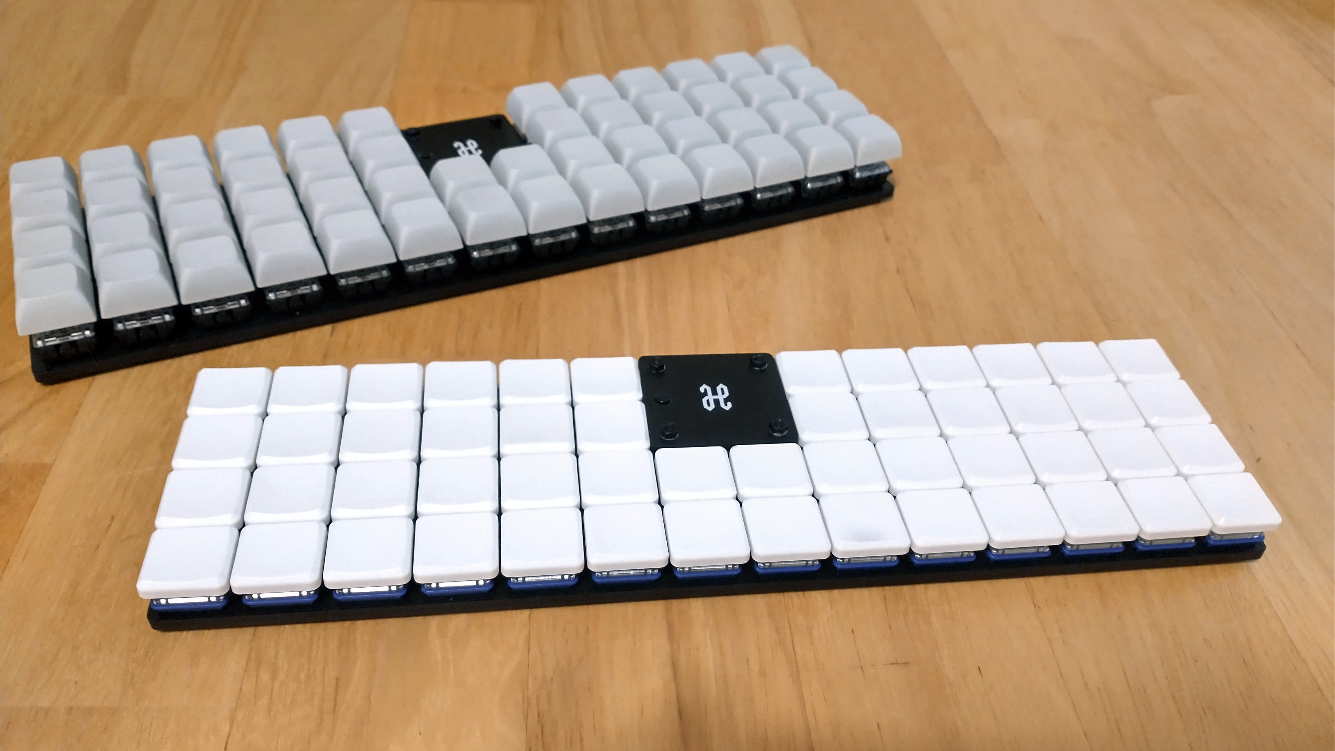
Horizon is a 52 key (4x14) ortholinear keyboard, powered by an Arduino Pro Micro.
This keyboard is a grid of 1U keys with no special features: no hotswap, no RGB, no OLED screen, no knobs.
gerbers: Gerber files for PCB manufacturinggraphics: Source assets for PCB silkscreenkicad: KiCad project files (schematics and PCB designs)kicad-libraries: KiCad components and footprintskicad-plugins: KiCad Pcbnew Python pluginsimages: Images for project documentationTwo separate PCB designs are available for MX and Choc keyswitches, with their respective footprints and key spacing (MX: 19mm x 19mm, Choc: 18mm x 17mm).
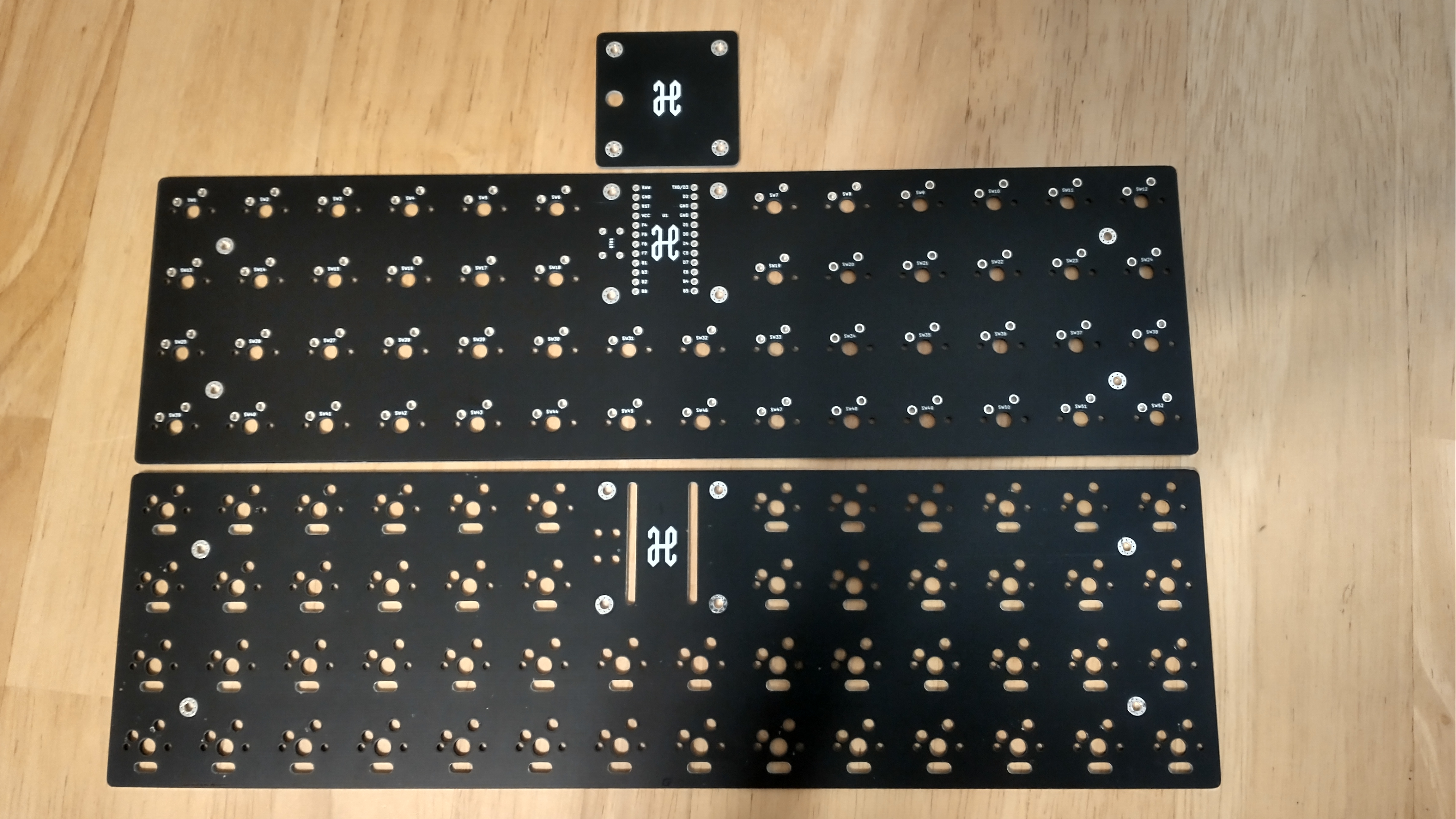
Each design consists of a main PCB, a top plate to protect the microcontroller, and a bottom plate to protect the bottom components:
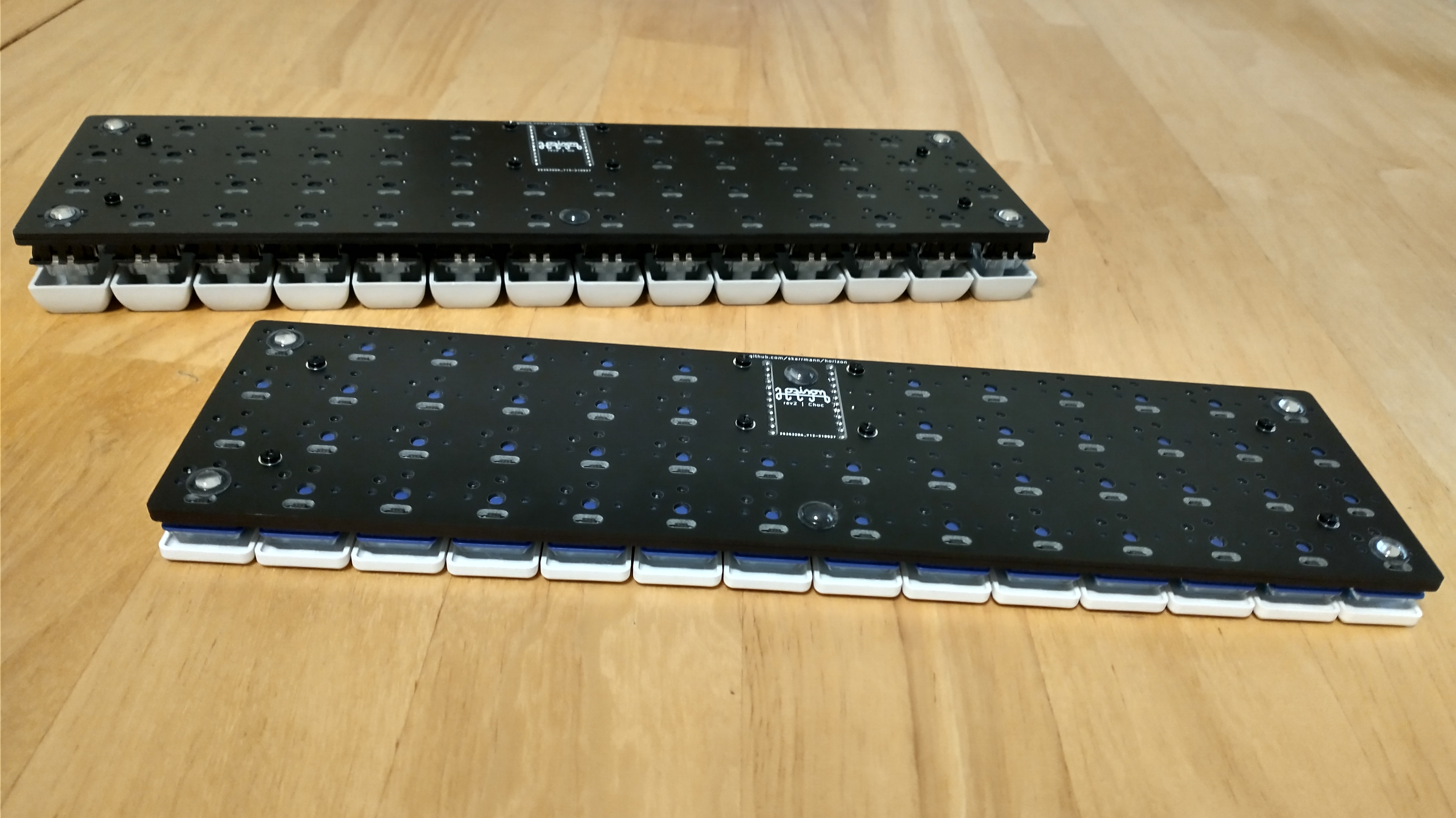
The bottom plate is a cutout of all the components exposed through the bottom of the main PCB, and screws directly against the main PCB. This nicely guards you and your desk surface from all the pointy through-hole bits, while retaining a low keyboard height:
The bottom and top plates are generated via a custom KiCad 7 Python SWIG plugin Horizon Board Producer.
For the plugin to generate these plate boards, the PCB and its footprints use the following layer convention:
F.Adhesive designates top plate holes and edge cuts.B.Adhesive designates bottom plate holes and edge cuts.When the board producer runs, these layers are used as follows:
Edge.Cuts when producing that plate.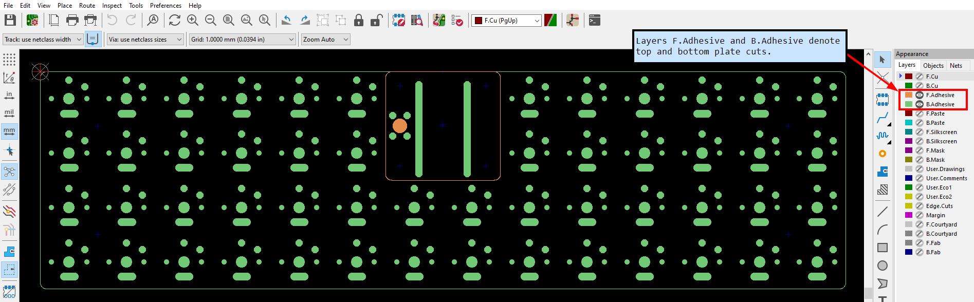
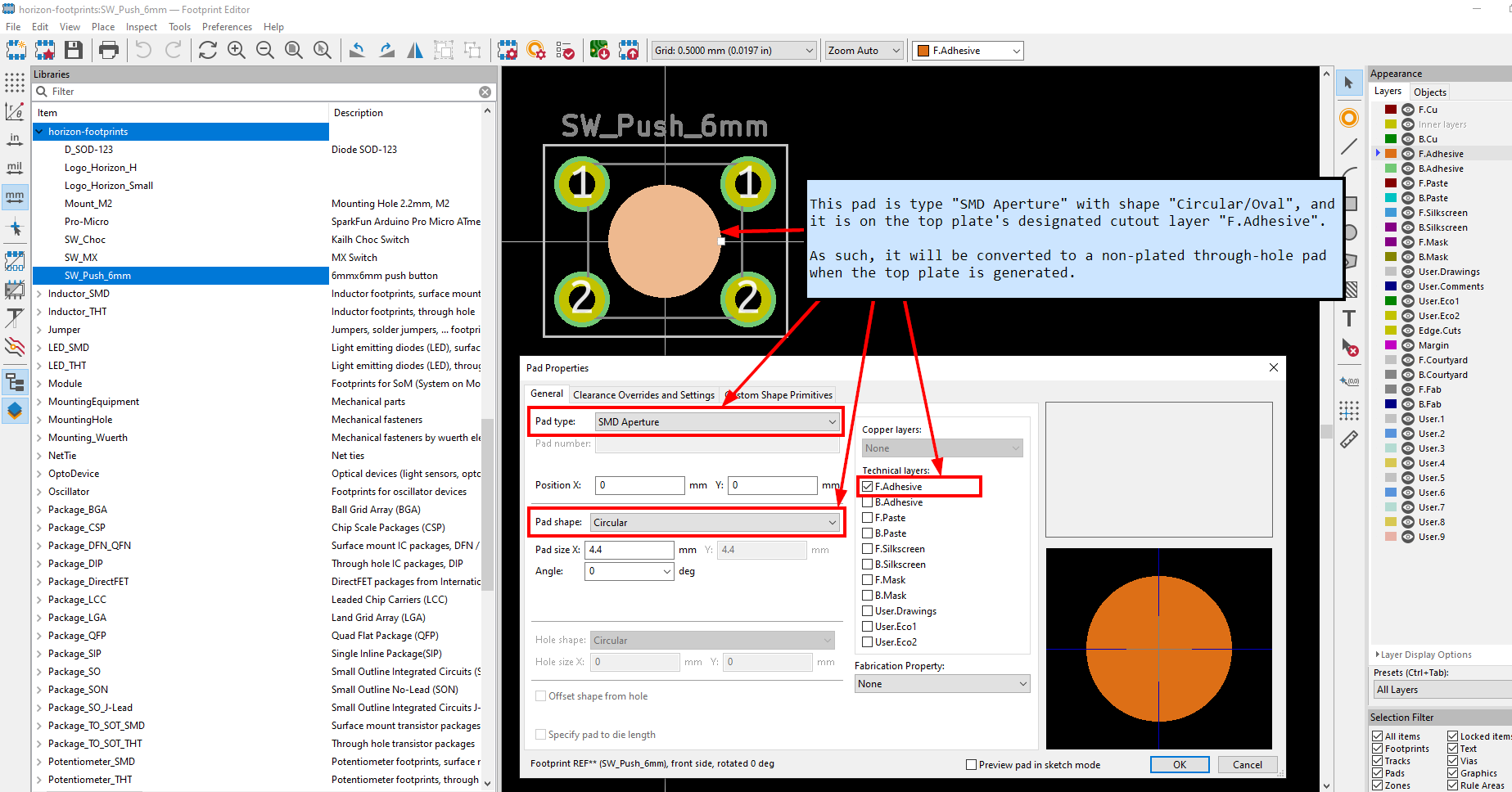
Additionally, the board producer plugin will preserve any in-bounds "H" footprint pads (mounting holes), "LOGO" footprint graphics (custom silkscreen art), and board silkscreen on the plates. Other items which are not needed for plates (e.g., copper tracks and zones) are removed from the plates.
The board producer plugin also generates all the Gerber files for production.
Please note the board producer plugin expects the following folder structure:
kicad/[board-version]/[board-name].kicad_pcbtemp is created in the project root to store any temporary files created.
IMPORTANT: If you would like to use this plugin and plate edge cuts convention for you own project, please make sure you carefully examine the output Gerber files! The plugin ultimately worked well for my case, but you might need to make adjustments to the plugin to suit your project. And to reduce the chance of being charged extra money by PCB manufacturers, use footprint plate holes instead of edge cuts whenever reasonable to do so.
IMPORTANT: This plugin uses pcbnew.LoadBoard() to load copies of the PCB, which is not safely supported in a running instance of KiCad. To avoid project integrity problems this may cause to the running KiCad instance, the plugin forcefully exits KiCad upon execution completion.
For PCBs, keyswitches, and keycaps, get parts depending on your desired keyswitch type.
| Part | Purpose | Quantity | Notes |
|---|---|---|---|
| Main PCB | circuit board | 1 | Send Gerber zip files to JLCPCB. |
| Top plate PCB | protects microcontroller | 1 | |
| Bottom plate PCB | protects bottom pins and components | 1 | |
| Arduino Pro Micro | Microcontroller board | 1 | Or use another Pro Micro compatible dev board with same dimensions (confirmed Elite-C V4, nice!nano 2.0, SuperMini nRF52840, and Adafruit KB2040 fit) |
| 6x6mm DIP 4-pin tactile switch | Reset button | 1 | |
| 1N4148 SOD-123 | Diodes for keyboard row-column matrix | 52 | |
| Keyswitches | 52 | PCB mount (5 pin) switches recommended. For MX, any switches should work. For Choc, get Choc V1 switches. | |
| Keycaps | 52 | For MX, any keycaps should work. For Choc, get those which fit Choc V1 18mm x 17mm | |
| M2 6mm screws | Secure main PCB and plate PCBs | 8 | |
| M2 nuts | Secure main PCB and plate PCBs | 8 | |
| M2 8mm male-female standoffs | Raise top plate PCB above microcontroller | 4 | |
| 2mm tall rubber bumpons | Raise board above desk surface and provide skid resitance | 6 |
I recommend using sockets for the Pro Micro. For socketing options, refer to 40% Keyboards' sockets article.
M2 standoff height requirements are dependent on the seated microcontroller height. An M2 spacer set should give you enough options. I recommend getting a reset button ~2mm taller than the M2 standoffs so the button is level with the top plate.
If using a bluetooth Pro Micro compatible dev board, then power it with battery size 301230. On the dev board, use sockets which provide at least 3mm clearance for the battery to fit underneath. Cut the battery wires so they are just long enough to poke through the B-/B+ pins from the underside of the dev board. Solder the battery's black wire to the B- pin, and the red wire to the B+ pin. Use a piece of Kapton or electrical tape to secure the battery to the dev board. When done, the dev board should look something like this:
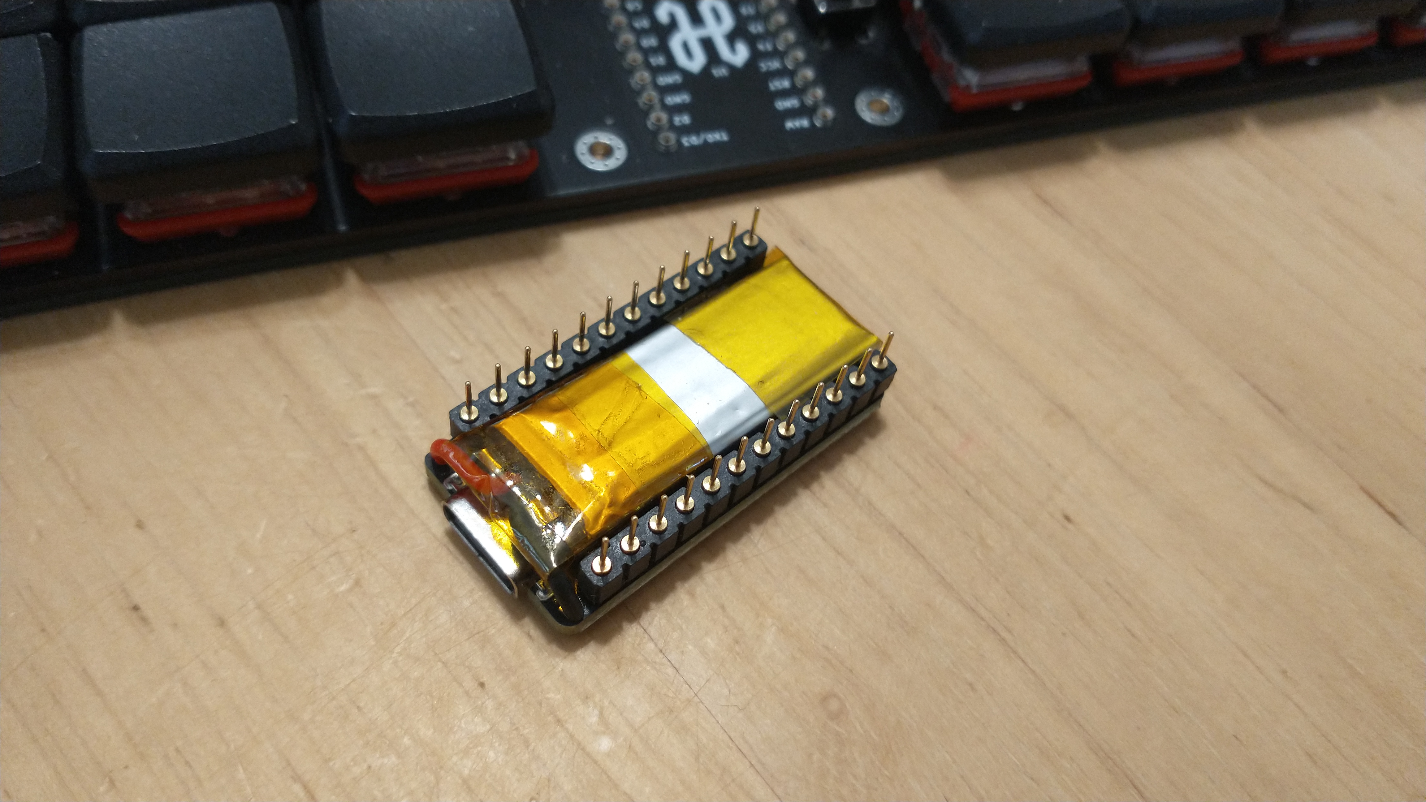
Horizon does not use a power switch or battery connector, so no other parts are needed when using a bluetooth Pro Micro compatible board. Since there is no physical power switch, refer to ZMK's power management configuration to manage power through firmware features.
These are the manufacturing settings I used when ordering from JLCPCB:
IMPORTANT: All PCBs have "JLCJLCJLCJLC" silkscreen text underneath the Pro Micro footprint. If you want to remove the order number from the boards or you want to print the PCBs with another manufacturer, then I recommend removing this silkscreen text from the .kicad_pcb file, and then re-run the Horizon Board Producer plugin to create the updated Gerber files.
| Qty | Value | Footprint | References |
|---|---|---|---|
| 52 | D | horizon-footprints:D_SOD-123 | D1, D2, D10, D11, D12, D13, D14, D15, D16, D17, D18, D19, D20, D21, D22, D23 +36 |
| 52 | SW_Push | horizon-footprints:SW_Choc | SW1, SW2, SW10, SW11, SW12, SW13, SW14, SW15, SW16, SW17, SW18, SW19, SW20, SW21, SW22, SW23 +36 |
| 8 | Hole_Pad | horizon-footprints:Mount_M2 | H1, H2, H3, H4, H5, H6, H7, H8 |
| 1 | Logo-Bottom | horizon-footprints:Logo_Horizon_Small | LOGO1 |
| 1 | Logo-Top | horizon-footprints:Logo_Horizon_H | LOGO2 |
| 1 | PRO-MICRO | horizon-footprints:Pro-Micro | U1 |
| 1 | RESET | horizon-footprints:SW_Push_6mm | BTN1 |

josefadamcik/SofleKeyboard
A split keyboard based on Lily58, Crkbd and Helix keyboards

TweetyDaBird/Lotus-58-Classic
A split ergo linear keyboard derived from the Lily58 family

joshajohnson/Hub16
A macro pad with 16 keys, two rotary encoders, a four port USB hub, and plenty of LEDs!

LouDnl/USBSID-Pico
USBSID-Pico is a RPi Pico (RP2040/W RP2350/W) based board for interfacing one or two MOS SID chips and/or hardware SID emulators over (WEB)USB with your computer, phone, ASID supporting player or USB midi controller

drfailov/DRM_Watch_v3
DRM Watch 3 - Наручний годинник з дисплеєм SHARP Memory LCD


It measures 252 × 68 mm and has 2 copper layers, 1.6 mm thick.
116 parts. The full list of its parts is on this page, with links to each part's symbol and footprint where PCBKit's library has them.
From the skarrmann/horizon repository on GitHub, at the commit this page was made from: the board is kicad/choc/horizon-choc.kicad_pcb and its schematic kicad/choc/horizon-choc.kicad_sch. PCBKit opens the board in the browser, with nothing to install.
Its repository publishes it under the MIT licence: you may reuse it on that licence's terms (keep the author's notice, and for a copyleft licence share your changes alike).