4 layers62.3 × 85.5 mm
20190720 Project OCP OVP UVP
simple-ee/mBMS
This is the modular BMS for use with 8S LiFePO4
97 parts8MIT
 simple-ee/mBMS8
This is the modular BMS for use with 8S LiFePO4
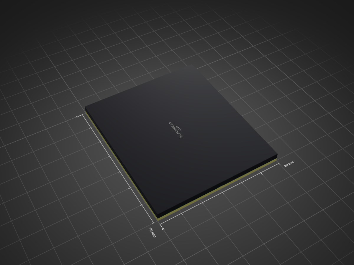
20210213 Projects PassiveBalanceBoard is an open-source printed circuit board by simple-ee, from the simple-ee/mBMS repository on GitHub, published under the MIT licence. It is a 2-layer board of 60 × 70 mm with 97 parts on 73 nets, routed with 913 tracks and 59 vias.
It is built around the MLFA1FTC10R0, CPF0603F100KC1 and RMCF0603ZT0R00, with the 2N7002-7-F-ES, BSS84LT1G and DMN3135LVT among its other parts. Its parts include 72 resistors, 24 transistors and 1 IC.


Just a reminder that this is a DIY product/solution so don’t use this for safety critical systems or in any situation where there could be a risk to life. There is no warranty, it may not work as expected or at all.
This is what I am calling the modular BMS for an 8S LiFePO4 pack. I've designed this as three main parts. Currently this design is functional and running my system but I am in the progress of overhauling the design by upgrading from an 8-bit ATmega328PB to a 32-bit SAMD21G18 using the arduino zero bootloader.
Right now I'm essentially maxed out resources and memory on the atmega328PB and cannot add anymore features which is why I'm planning on upgrading the design.
Even though this design is now my old design its still very functional and very stable as it has been running my 4kWh system for about 6 months and protecting the cells perfectly.
The reason for making it a modular design is for easy upgradability and also, considering the current chip shortage, is to replace sections of the board in case there are no parts available. This will prevent the need to redo and re-layout of the entire design.
I'm posting this design because I've learned a lot from other projects and feel this will help a lot of people and want to give back. Also smarter people than me could take this design and help optomize the code and design and make this a community BMS.
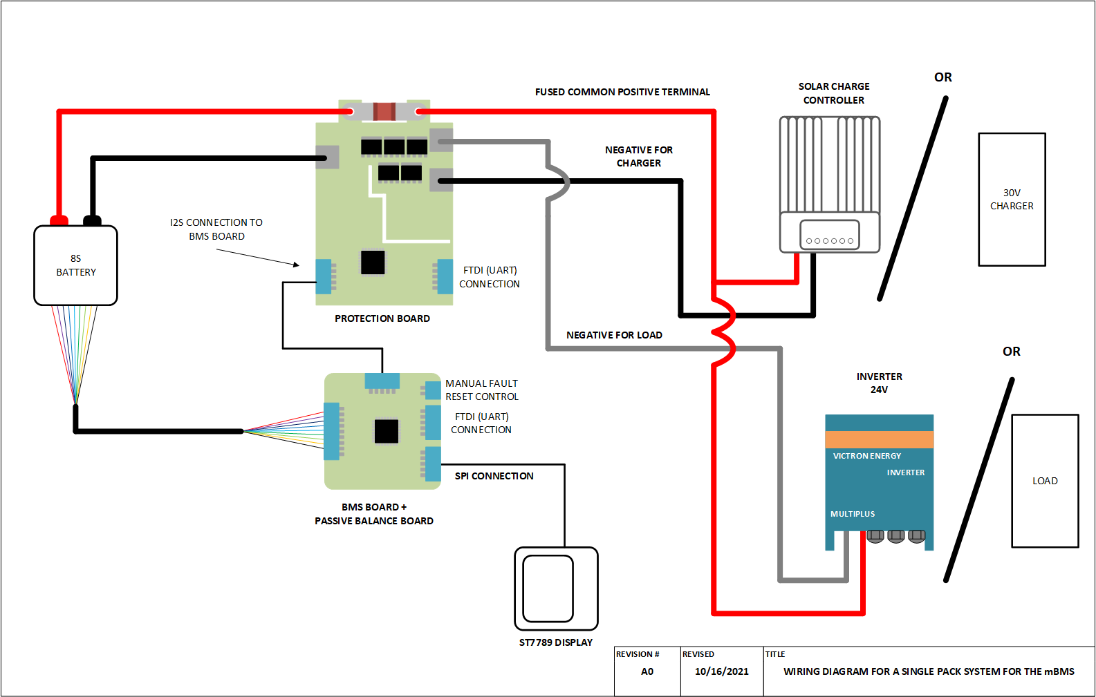
Here we have the wiring diagram for connecting the mBMS to an 8S pack and is considered a single pack system:
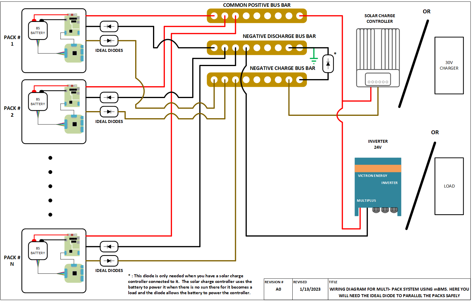
Here we have the wiring diagram for connecting multiple 8S packs in parallel. Here each 8S pack is protected by its own mBMS and then they are paralleled together using ideal diodes to make sure that the other packs in parallel do not charge or discharge a pack that has gone into protection. I designed the system this way to allow for scalability of system storage. By protecting each pack separately then you can, theoretically, add tens of hundreds of 8S packs in parallel when you need more storage without having to reconfigure your system to add more storage or turn off the system to add more storage.
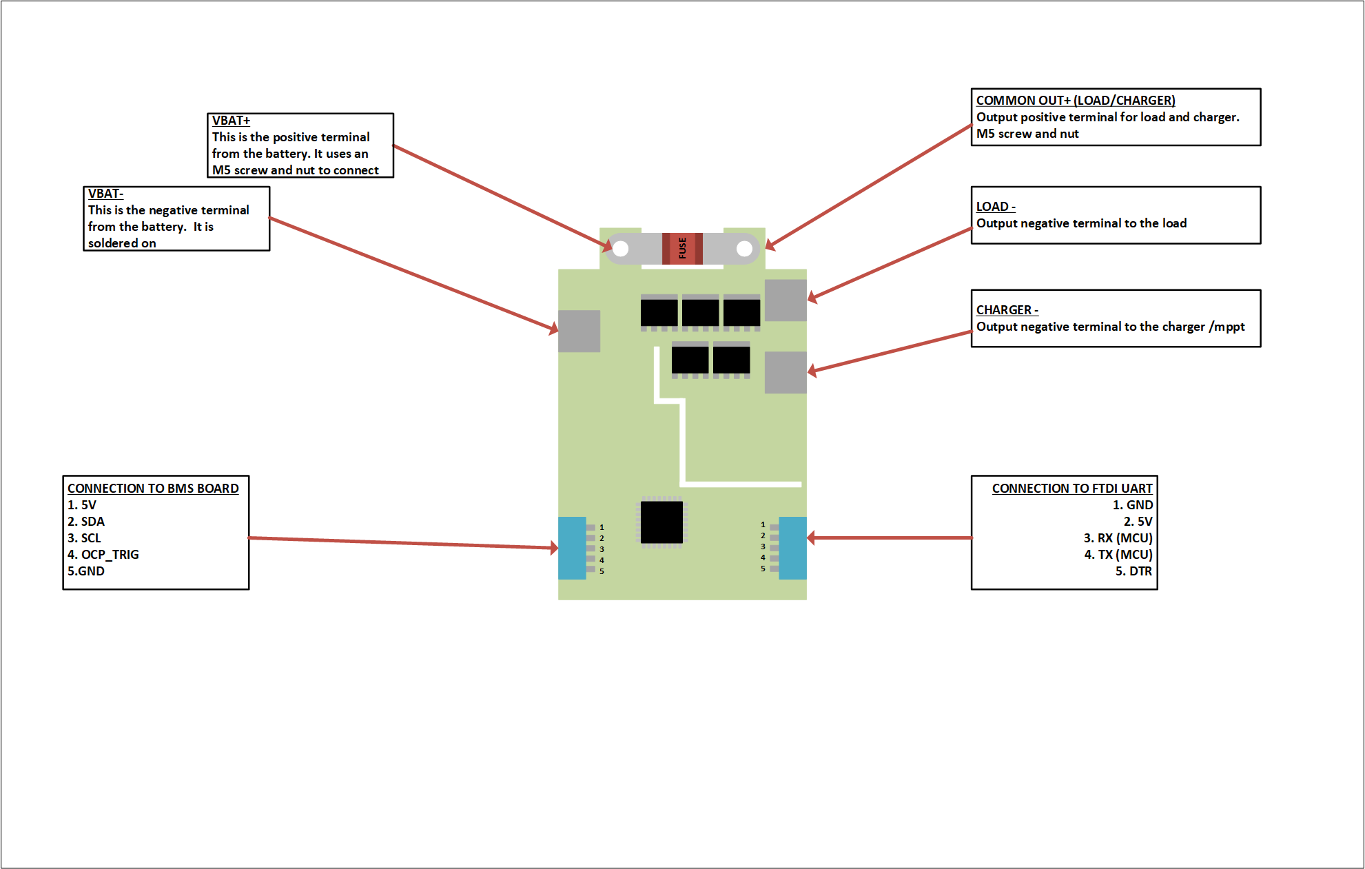
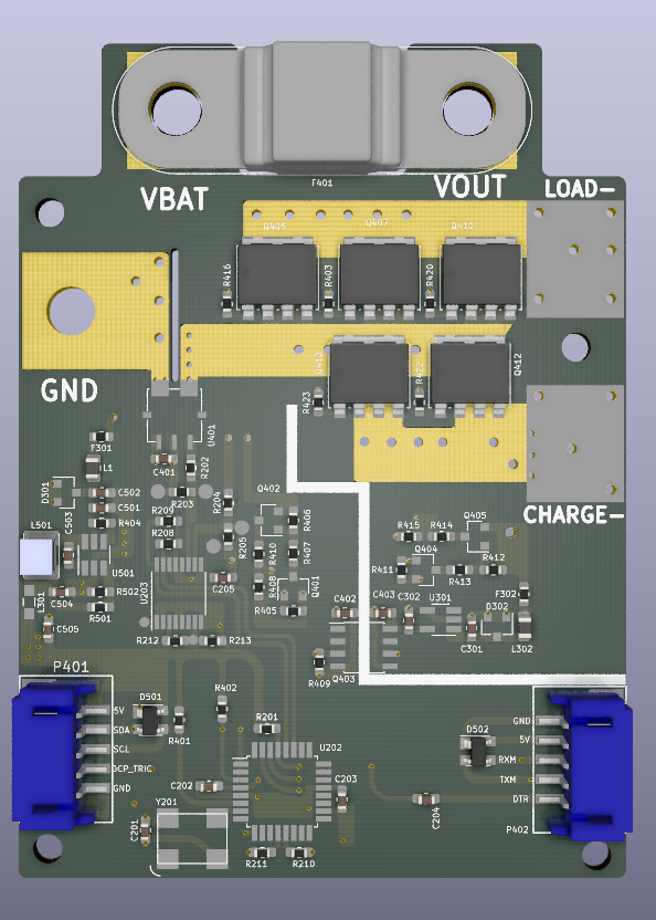
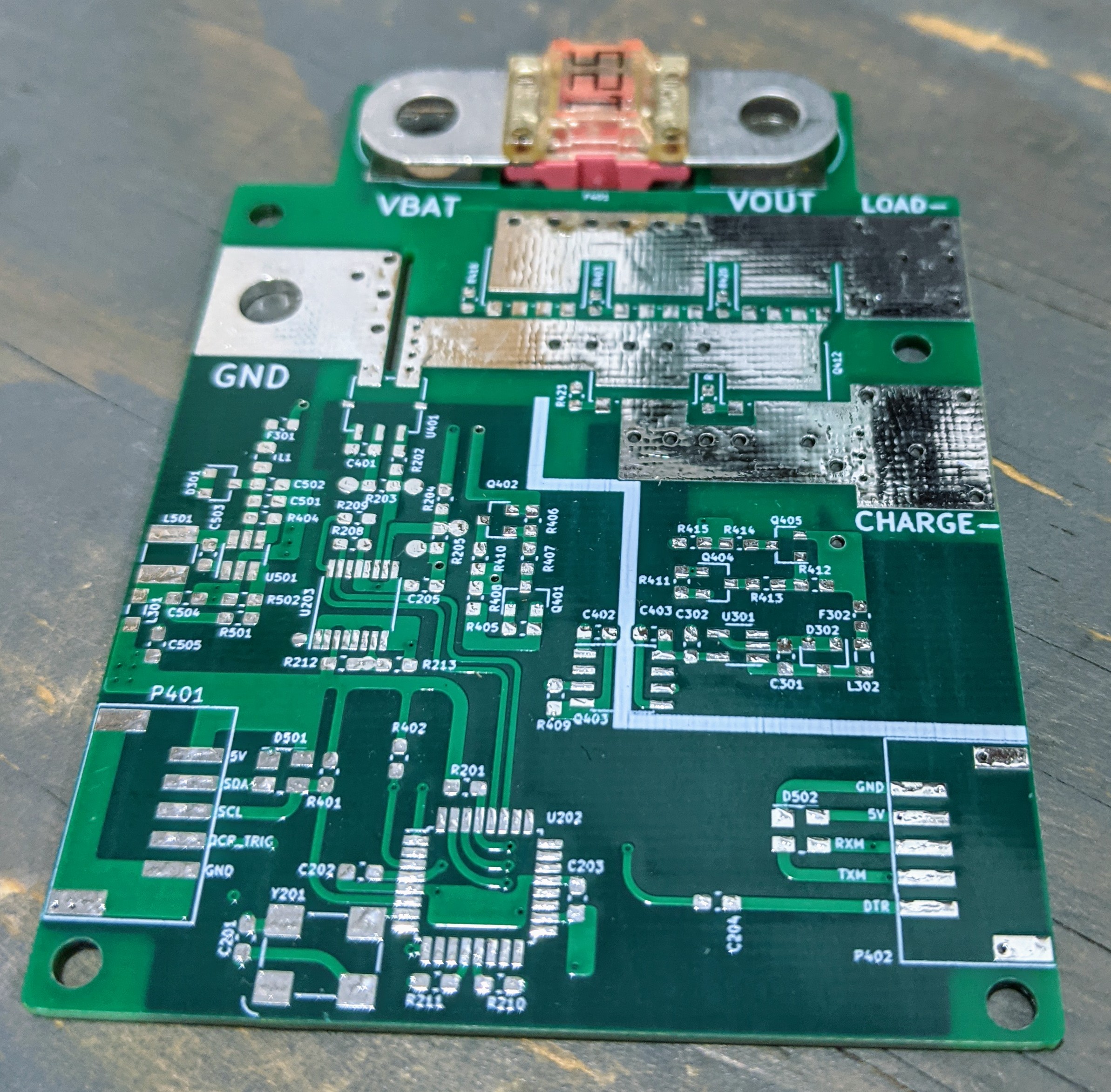
This board will handle discharge and charge currents between the battery and the external world.
It has the following specs:
| Item | Description |
|---|---|
| 1 | 4-Channel 16-BIT ADC with an effective resolution of 16-Bit at 20sps |
| 2 | 100A hall effect current sensor |
| 3 | Up to 3 Discharge N-Channel MOSFETS with 0.7mOhm DCR and 425A current capability. ( Effective current handling per mosfet without heatsink is 30A) |
| 4 | Up to 2 charge N-Channle MOSFETS with 0.7mOhm DCR and 425A current capability. (Effective current handling per mosfet without heatsink is 30A) |
| 5 | Optoisolator to drive the charge mosfets as it is floating relative to the battery ground. |
| 6 | High efficiency buck converter to power the MCU and supporting circuits. |
| 7 | Low power LDO to power the secondary side of the optoisolator to drive the charge MOSFET |
| 8 | Two I2C ports, one to act as an internal COM for adc and display, andsecond one to act as external COM to relay information to BMS board |
| 9 | 125A fuse that will act as the short circuit protection with a breaking capacity of 1kA. |
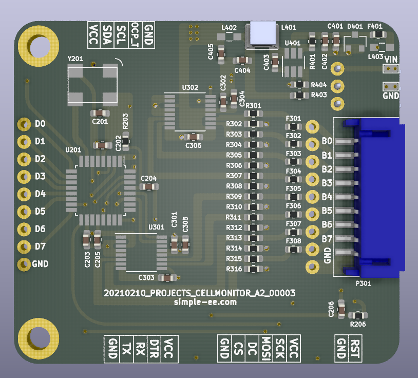
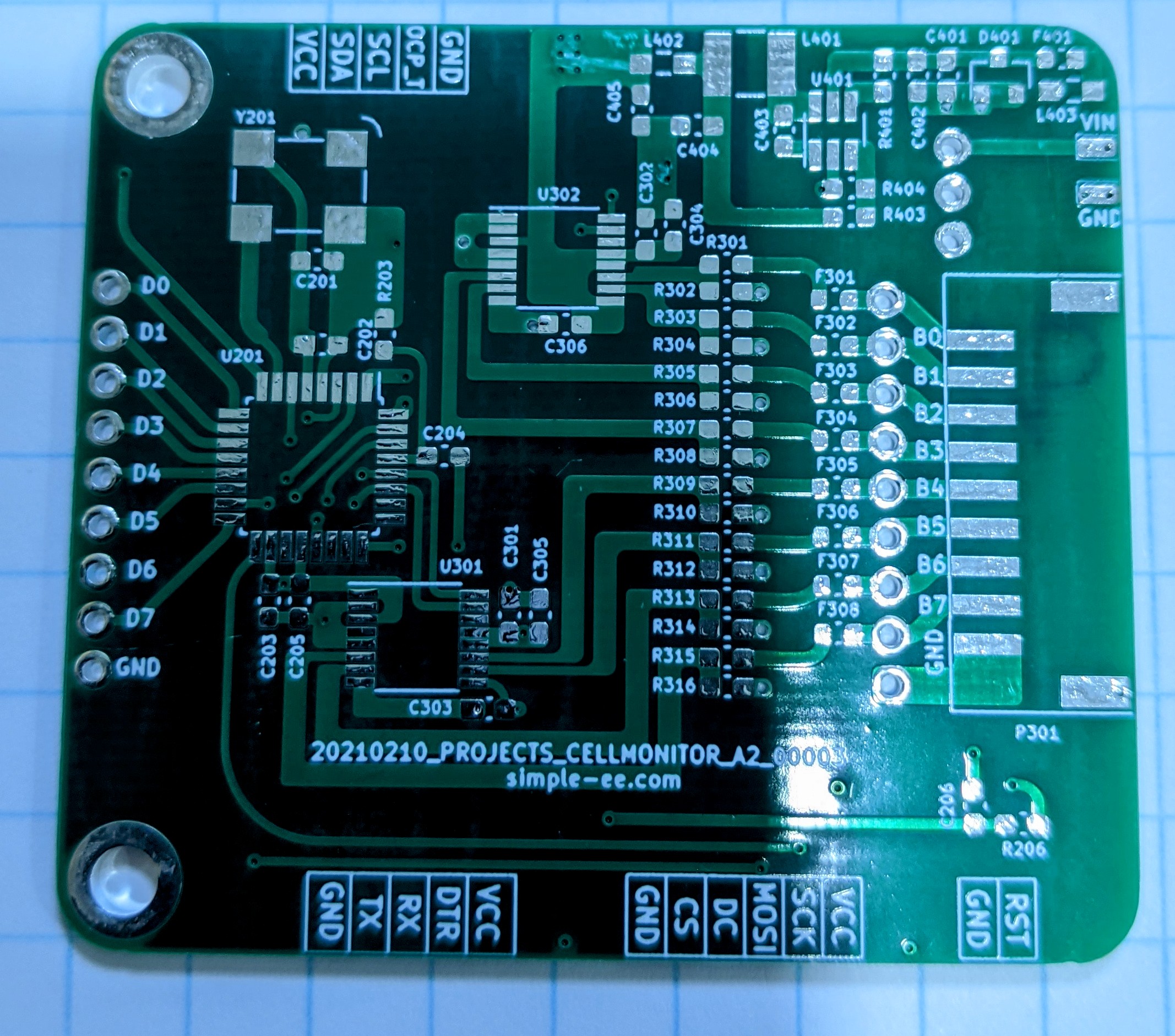
| Item | Description |
|---|---|
| 1 | x2 4-Channel 16-BIT ADC with an effective resolution of 16-BIT at 20sps |
| 2 | External 16MHz Crystal oscillator |
| 3 | External SPI port to connect TFT display |
| 4 | Can be powered via the battery pack or external power source |
| 5 | External action button. Default state is for reset fault condition |
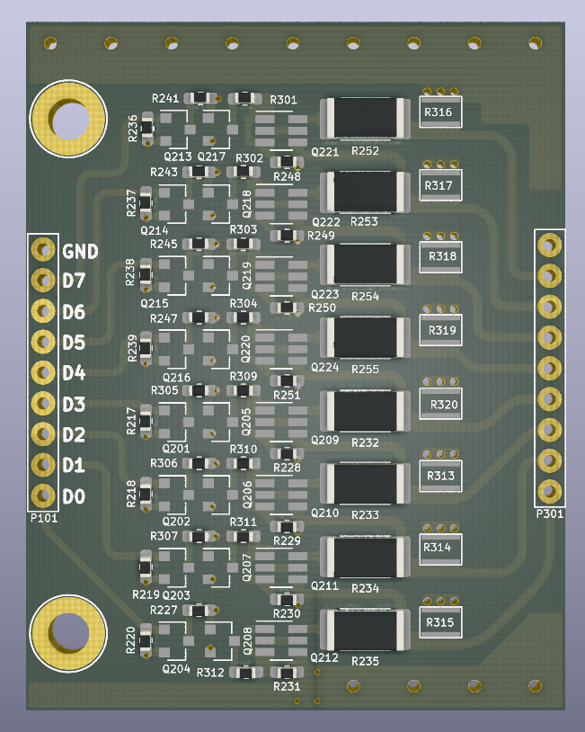
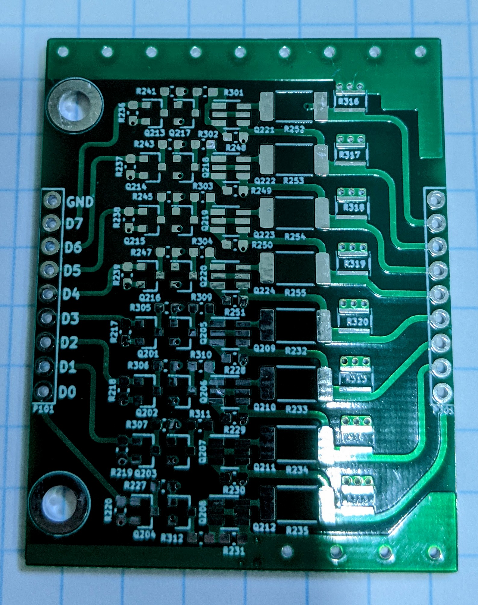
The passive board essentially is controlled by the BMS board to allow the bleeder resistor to slow down the rate of charge for that particular cell when the BMS board detects that the cell is too high of a delta from the rest.
Currently I have a 2W 10R resistor but I'm having thermal issues because its quite a lot of power to dissapate over the whole board so I'd recommend a 22R 2W resistor which is still good for what you need but will not cause any potential damage.
The board also have the option of adding thermal jumpers and if you do decide to do that then I'd recommend a 2oz copper for that PCB. Thermal jumpers are electrically isolated and allow you to connect directly to ground without shorting anything which is pretty awesome in my opinion.
Heres the link for the thermal jumpers. They are really awesome but with the chip shortage its a decent lead time for them.
https://www.digikey.com/en/products/detail/vishay-dale-thin-film/THJP0612AST1/11313314
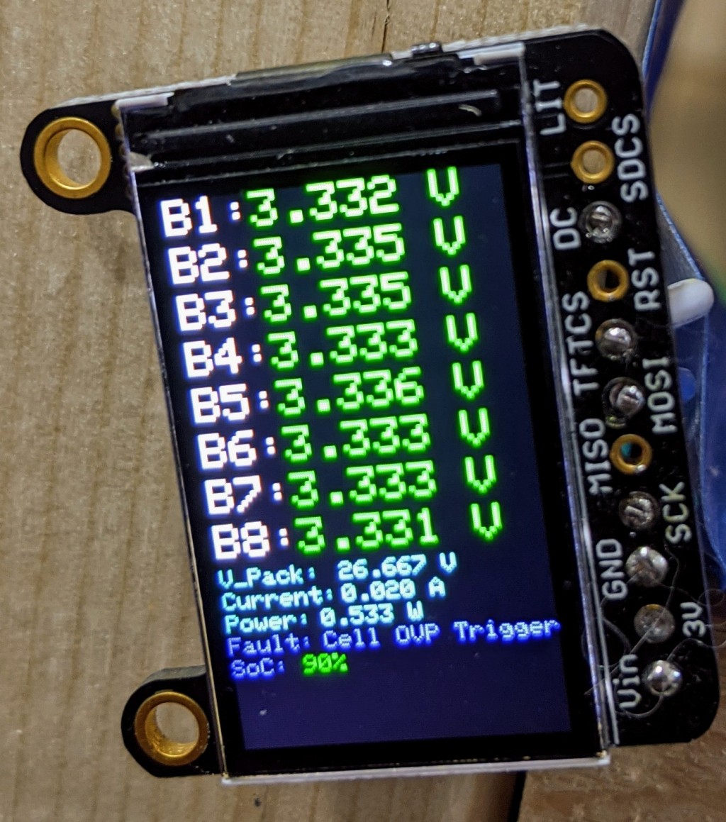
Currently the SoC is not an implemented function its just a placeholder. But if anyone is willing to help out with this SoC code section then that would be awesome as I'm still not sure the best way to implement this.
The screen is to be used with the BMS board. the Protection does not have the ability to use a SPI TFT display but if you use it on its own, then you can add an I2C oled display because the secondary I2C will not be used.
Here is a link to the tft display that I used. https://www.adafruit.com/product/4383
| Qty | Value | Footprint | References |
|---|---|---|---|
| 32 | MLFA1FTC10R0 | Passives:R_MELF_0207 | R313, R314, R315, R316, R317, R318, R319, R320, R321, R322, R323, R324, R325, R326, R327, R328 +16 |
| 31 | CPF0603F100KC1 | Passives:R_0603_Handsolder | R217, R218, R219, R220, R221, R223, R225, R228, R229, R230, R231, R236, R237, R238, R239, R240 +15 |
| 9 | RMCF0603ZT0R00 | Passives:R_0603_Handsolder | R227, R301, R302, R303, R304, R309, R310, R311, R312 |
| 8 | 2N7002-7-F | SOT:SOT-23-3 | Q201, Q202, Q203, Q204, Q213, Q214, Q215, Q216 |
| 8 | BSS84LT1G | SOT:SOT-23-3 | Q205, Q206, Q207, Q208, Q217, Q218, Q219, Q220 |
| 8 | DMN3135LVT | SOT:SOT-23-6 | Q209, Q210, Q211, Q212, Q221, Q222, Q223, Q224 |
| 1 | 8S_PASSIVE_V2 | Modules:8S_PASSIVE_V2 | U101 |
simple-ee/mBMS
This is the modular BMS for use with 8S LiFePO4


fsodari/USBAudioBridge
NXP RT1010 based USB to I2S bridge to connect to a Digilent Arty A7.

MukeshSethy/micromouse-runner
This is my repo for the first version of full size micromouse development.


YingK8/ESP32-BLE-Macro-Pad
A compact, programmable macropad with Bluetooth connectivity, featuring 6 mechanical keys and a rotary encoder for media control.


oresat/oresat-c3-hardware
C3 (Command, Communication, and Control) our Command and Data Handling (C&DH) card.
It measures 60 × 70 mm and has 2 copper layers, 1.6 mm thick.
97 parts, built around the MLFA1FTC10R0, CPF0603F100KC1, RMCF0603ZT0R00 and 2N7002-7-F-ES. The full list of its parts is on this page, with links to each part's symbol and footprint where PCBKit's library has them.
From the simple-ee/mBMS repository on GitHub, at the commit this page was made from: the board is Schematic/The Passive Balance Board/20210213_Projects_PassiveBalanceBoard.kicad_pcb. PCBKit opens the board in the browser, with nothing to install.
Its repository publishes it under the MIT licence: you may reuse it on that licence's terms (keep the author's notice, and for a copyleft licence share your changes alike).