2 layers56.5 × 29 mm
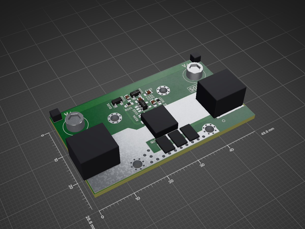
 simple-ee/Power_CircuitDesigns2
2021 Project OCP Ideal Diode is an open-source printed circuit board by simple-ee, from the simple-ee/Power_CircuitDesigns repository on GitHub. It is a 2-layer board of 49.8 × 28.8 mm with 25 parts on 8 nets, routed with 91 tracks and 18 vias.
It is built around the THJP0612AST1, DESD34VS2SO and PSMNR70-40SSHJ, with the RMCF0603FT300K among its other parts. Its parts include 8 connectors, 7 resistors, 4 capacitors, 2 ICs and 1 diode.


| Qty | Value | Footprint | References |
|---|---|---|---|
| 4 | MH_1POS_2.5MM | MountingHoles_sg:MountingHole_2.5mm_Pad_Via | P105, P106, P107, P108 |
| 3 | THJP0612AST1 | ThermalJumper:THJP0612AST1 | R102, R103, R106 |
| 2 | 2.5x2.5mm_pad | Terminal Blocks:pad_2.5x2.5mm | P101, P103 |
| 2 | 7460305 | Terminal Blocks:7460305_HASL | P102, P104 |
| 2 | RC0603FR-07470RL | Passives:R_0603_Handsolder | R104, R105 |
| 1 | C0603C104K5RACAUTO | Passives:C_0603_Handsolder | C103 |
| 1 | C0603C331J5GACTU | Passives:C_0603_Handsolder | C104 |
| 1 | CL10A105KB8NNNC | Passives:C_0603_Handsolder | C102 |
| 1 | CL10X106MO8NRNC | Passives:C_0603_Handsolder | C101 |
| 1 | DESD34VS2SO | SOT:SOT-23-3 | D101 |
| 1 | MCP6V51T-E_OT | SOT:SOT-23-5_HandSoldering | U102 |
| 1 | PSMNR70-40SSHJ | SOT:SOT-1235 | Q101 |
| 1 | RC0603FR-0716RL | Passives:R_0603_Handsolder | R101 |
| 1 | RMCF0603FT300K | Passives:R_0603_Handsolder | R107 |
| 1 | ZXTR2112F-7 | SOT:SOT-23-3 | U101 |
The 23 most common of 25 parts.

simple-ee/mBMS
This is the modular BMS for use with 8S LiFePO4

drpykachu/Sonar-Watch
A self-designed, home-made watch intended to tell time in a funky and unique way!


TENNLab-UTK/NWRIST
Code and KiCAD PCB design for the NWRIST: Neuromorphic Wearable for Real-Time Intelligent Sensing Technology paper

google/mozc-devices
Circuit diagrams and firmware source code for Gboard DIY keyboards

davidphilipbarr/Sweep
Sweep - a small promicro based keyboard inspired by the Ferris.


hackclub/OnBoard
💡 Join 1,000 teenagers and make your first PCB with a $100 grant!
It measures 49.8 × 28.8 mm and has 2 copper layers, 1.6 mm thick.
25 parts, built around the THJP0612AST1, DESD34VS2SO, PSMNR70-40SSHJ and RMCF0603FT300K. The full list of its parts is on this page, with links to each part's symbol and footprint where PCBKit's library has them.
From the simple-ee/Power_CircuitDesigns repository on GitHub, at the commit this page was made from: the board is Ideal Diode/Source Files/2021_Project_OCP_Ideal_Diode.kicad_pcb and its schematic Ideal Diode (LM5051 version)/Source Files/20220727_Projects_Ideal_Diode_02.kicad_sch. PCBKit opens the board in the browser, with nothing to install.
Its repository states no licence, so its author keeps all rights: ask simple-ee before reusing the design.