2 layers
Encoder
byrantech/laptop
anyon_e, a highly integrated, high end, open source laptop. Attempt the impossible.
7 parts4.3kMIT
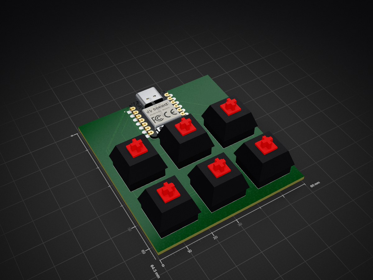
 Silvonik/Hackpad
Instead of pressing ctrl and c to copy or ctrl and s to save I now only need to press one key on the Hackpad.
Hackpad is an open-source printed circuit board by Silvonik, from the Silvonik/Hackpad repository on GitHub. It is a 2-layer board of 60 × 64.5 mm with 7 parts on 14 nets, routed with 50 tracks and 0 vias.
Its parts include 6 switches and 1 IC.
The Hackpad is a custom macropad to help me with everyday repetitive keyboard shorcuts.
Instead of pressing ctrl and c to copy or ctrl and s to save I now only need to press one key on the Hackpad.
The point of the Hackpad was to teach me how to make hardware and also to let me avoid getting my hands to awkward positions just to undo or save my code.
To make the Hackpad I needed to learn how to make a Schematic, PCB, and Case, but the problem was I never done it before so first thing I did is come up with the idea of what the Hackpad will do, after I came up with the idea of the shortcuts. Then I the got to work by making the schematic, to make it I followed the guide and asked questions to the Hackpad Channel on Slack. When the schematic was finished I turned it into a PCB, I enjoyed working on the PCB it is very relaxing but not really when you run into problems. After The PCB I worked on the Case, I installed Fusion360 for the first time and started making the case, The case took me the longest because I kept having to reset or go back and change stuff and it was very confusing to me as a beginner. After all of that I went to sleep and in the morning worked on the Firmware. the firmware was okay because I used Arduino IDE which I previously used before, when finished the code I quickly compiled it to check if it worked which it did not but after some deubuging everything worked. After an eternity I finally got all the parts needed to assemble the Hackpad, first I soldered the header pins to the Xiao RP2040, after I uploaded the firmware and tested the circuit with a breadboard and it worked, then I put all the parts on the PCB and I soldered them on, when I finished that I tried to put in inside the case with the cover but it didn't fit so I had to remodel the case and 3D print a new one, so after all of that I now have a macropad which I use daily and It came out AMAZING!
Ctrl A = All, Ctrl C = copy, Ctrl V = paste, Ctrl S = save, Ctrl Z = undo, Ctrl Y = Redo.
It was very hard learning everything from scratch like how to make a schematic, pcb, a case but I managed and I couldn't have done it without yam he helped me so much with like bugs and common problems my beginner brain didn't now how to solve.
When building the Hackpad I learned how to make a PCB, use Kicad, make a schematic, use Fusion360 to make the case and how to actually solder. These skills will help me in my future hardware projects so much!


| Qty | Value | Footprint | References |
|---|---|---|---|
| 6 | SW_Push | Button_Switch_Keyboard:SW_Cherry_MX_1.00u_PCB | SW1, SW2, SW3, SW4, SW5, SW6 |
| 1 | MOUDLE-SEEEDUINO-XIAO | footprints:XIAO-Generic-Hybrid-14P-2.54-21X17.8MM | U1 |
It measures 60 × 64.5 mm and has 2 copper layers, 1.6 mm thick.
7 parts. The full list of its parts is on this page, with links to each part's symbol and footprint where PCBKit's library has them.
From the Silvonik/Hackpad repository on GitHub, at the commit this page was made from: the board is PCB/Hackpad/Hackpad.kicad_pcb and its schematic PCB/Hackpad/Hackpad.kicad_sch. PCBKit opens the board in the browser, with nothing to install.
Its repository states no licence, so its author keeps all rights: ask Silvonik before reusing the design.
byrantech/laptop
anyon_e, a highly integrated, high end, open source laptop. Attempt the impossible.


AxxAxx/AxxSolder
STM32 Based soldering station for JBC cartridges, 9-24 VDC and USB-PD power


jamro/tiny-engineer
A small desktop robot that brings an AI coding assistant to life, physically acting out when it reads files, thinks, writes code, and finishes work.

hoglet67/RGBtoHDMI
Bare-metal Raspberry Pi project that provides pixel-perfect sampling of Retro Computer RGB/YUV video and conversion to HDMI
