2 layers182.2 × 116.6 mm
 sideburn/GamesMachine
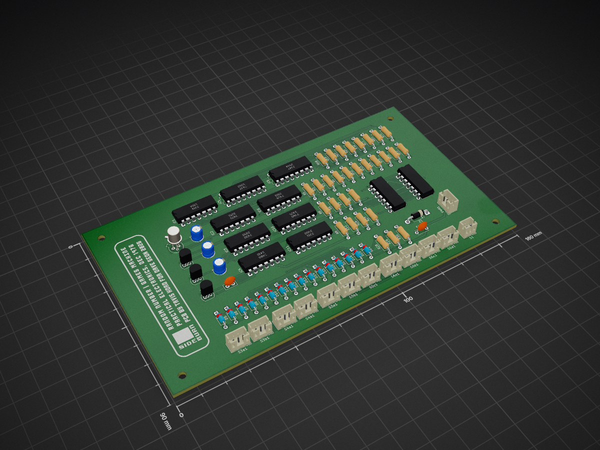
Random Number Games Machine — Sideburn Studios rev 2.0, from Practical Electronics Dec 1976 (D. Burn)
GamesMachine is an open-source printed circuit board by sideburn, from the sideburn/GamesMachine repository on GitHub. It is a 2-layer board of 160 × 90 mm with 84 parts on 92 nets, routed with 791 tracks and 47 vias.
Its parts include 30 resistors, 16 diodes, 12 switches, 9 ICs and 4 capacitors.
KiCad recreation of "Games Machine — a programmed random number generator" by D. Burn, Practical Electronics, December 1976 (pp. 969–975). PCB by Sideburn Studios.
A TTL-logic random number generator with four selectable modes:
| Mode | Range | Zero behaviour |
|---|---|---|
| Random | 0–99 | 00 allowed |
| Roulette | 0–36 | 00 allowed |
| Pools | 1–59 | single zero allowed, 00 blocked |
| Dice | 1–6 per digit | no zero in either digit |
Randomness comes from an avalanche-noise transistor (TR1) feeding a two-stage amplifier (TR2, TR3), squared by a 7413 Schmitt trigger, and gated into a pair of 7490 decade counters while a 2N2646 UJT relaxation oscillator (TR4) free-runs at 3–4 s. Because the operator's press and the oscillator phase are uncorrelated, the stopping point is unpredictable. Game ranges and the zero-detector restart logic come from a diode-resistor matrix (D5–D20) read through an interlocked pushbutton bank (S1, S3–S6).
Rev 1.0 — fabricated 2026-07-09, built and fully bench-tested. All four game modes verified working against the behaviour described in the original article. Three defects were found and worked around on the physical board (see below).
Rev 2.0 — all fixes applied to the KiCad source, DRC clean (0 violations, 0 unconnected), gerbers and drill files regenerated. Ready to order; not yet fabricated.
| # | Issue | Resolution |
|---|---|---|
| 1 | LOGIC_0 was a floating net, never tied to ground — board freezes at 99 | Merged into GND |
| 2 | Diode silkscreen band marked the anode, so all 17 diodes fitted backwards to the print | Symbol pin numbers swapped, diodes rotated 180° |
| 3 | UNITS/TENS displays placed in reverse reading order — digits read transposed | Placements exchanged |
| 4 | 2N2926 symbol declared E-B-C; the real part is E-C-B, so TR1–TR3 needed crossed leads | Pin numbers corrected |
| 5 | TR4 (2N2646) footprint mapping suspected wrong | Verified correct as drawn — no change |
Full detail, including what was deliberately left alone, is in Docs/Rev2_Board_Fixes.md.
GamesMachine.kicad_sch / .kicad_pcb / .kicad_pro — the KiCad projectGamesMachine.kicad_sym — project-local symbol library (custom parts)GamesMachine.stl — 3D case/board modelGerbers/ — fabrication output, regenerated for rev 2.0Docs/PartsList.md — full parts list with sourcing notesDocs/BOM.csv — machine-readable BOM exported from the schematicDocs/BringUp_TestPlan.md — staged bring-up and test procedureDocs/GameMode_Jumper_Reference.md — switch/jumper configuration per game modeDocs/Rev2_Board_Fixes.md — defect record and how each was resolvedThe first commit is the rev 1.0 project exactly as fabricated, so the whole set of fixes can be read as a diff against the board that was actually built.
Practical Electronics, Vol. 12 No. 12, December 1976. Article by D. Burn, PhD. The magazine scan is not redistributed here.
| Qty | Value | Footprint | References |
|---|---|---|---|
| 16 | 1N914 | Diode_THT:D_DO-35_SOD27_P7.62mm_Horizontal | D5, D6, D7, D8, D9, D10, D11, D12, D13, D14, D15, D16, D17, D18, D19, D20 |
| 14 | 270 | Resistor_THT:R_Axial_DIN0207_L6.3mm_D2.5mm_P10.16mm_Horizontal | R11, R12, R13, R14, R15, R16, R17, R18, R19, R20, R21, R22, R23, R24 |
| 11 | SPDT | Connector_JST:JST_PH_B3B-PH-K_1x03_P2.00mm_Vertical | S3a1, S3b1, S4a1, S4b1, S5a1, S5b1, S5c1, S6a1, S6b1, S6c1, S6d1 |
| 6 | 1k | Resistor_THT:R_Axial_DIN0207_L6.3mm_D2.5mm_P10.16mm_Horizontal | R25, R26, R27, R28, R29, R30 |
| 4 | 4.7k | Resistor_THT:R_Axial_DIN0207_L6.3mm_D2.5mm_P10.16mm_Horizontal | R2, R8, R9, R10 |
| 4 | MountingHole_3mm | MountingHole:MountingHole_3mm | BLMH, BRMH, TLMH, TRMH |
| 3 | 10uF | Capacitor_THT:CP_Radial_D5.0mm_P2.50mm | C1, C2, C4 |
| 3 | 2N2926 | Package_TO_SOT_THT:TO-92_Inline | TR1, TR2, TR3 |
| 2 | 2.2k | Resistor_THT:R_Axial_DIN0207_L6.3mm_D2.5mm_P10.16mm_Horizontal | R4, R5 |
| 2 | 7447 | Package_DIP:DIP-16_W7.62mm | IC5, IC6 |
| 2 | 7490 | Package_DIP:DIP-14_W7.62mm | IC3, IC4 |
| 1 | 0.1uF | Capacitor_THT:C_Disc_D5.0mm_W2.5mm_P2.50mm | C3 |
| 1 | 100k | Resistor_THT:R_Axial_DIN0207_L6.3mm_D2.5mm_P10.16mm_Horizontal | R3 |
| 1 | 150k | Resistor_THT:R_Axial_DIN0207_L6.3mm_D2.5mm_P10.16mm_Horizontal | R6 |
| 1 | 1N4733A_5.1V | Diode_THT:D_DO-41_SOD81_P10.16mm_Horizontal | Z1 |
| 1 | 220 | Resistor_THT:R_Axial_DIN0207_L6.3mm_D2.5mm_P10.16mm_Horizontal | R7 |
| 1 | 2N2646 | Package_TO_SOT_THT:TO-18-3 | TR4 |
| 1 | 47k | Resistor_THT:R_Axial_DIN0207_L6.3mm_D2.5mm_P10.16mm_Horizontal | R1 |
| 1 | 7412 | Package_DIP:DIP-14_W7.62mm | IC11 |
| 1 | 7413 | Package_DIP:DIP-14_W7.62mm | IC1 |
| 1 | 7425 | Package_DIP:DIP-14_W7.62mm | IC9 |
| 1 | 7472 | Package_DIP:DIP-14_W7.62mm | IC2 |
| 1 | 7480 | Package_DIP:DIP-14_W7.62mm | IC10 |
| 1 | POWER_JST_PH3 | Connector_JST:JST_PH_B3B-PH-K_1x03_P2.00mm_Vertical | PWR1 |
| 1 | PTC_0.5A | Capacitor_THT:C_Disc_D5.0mm_W2.5mm_P5.00mm | F1 |
| 1 | SPDT | Connector_JST:JST_PH_B2B-PH-K_1x02_P2.00mm_Vertical | S1 |
| 1 | TENS_DISP_SOCKET | Package_DIP:DIP-14_W7.62mm | TENS1 |
| 1 | UNITS_DISP_SOCKET | Package_DIP:DIP-14_W7.62mm | UNITS1 |
It measures 160 × 90 mm and has 2 copper layers, 1.6 mm thick.
84 parts. The full list of its parts is on this page, with links to each part's symbol and footprint where PCBKit's library has them.
From the sideburn/GamesMachine repository on GitHub, at the commit this page was made from: the board is GamesMachine.kicad_pcb and its schematic GamesMachine copy.kicad_sch. PCBKit opens the board in the browser, with nothing to install.
Its repository states no licence, so its author keeps all rights: ask sideburn before reusing the design.

pcbreflux/espressif
all espressif stuff will committed here

CRImier/MyKiCad
My KiCad boards. Can't be bothered uploading individually anymore, so here you go.


Rack-Robotics/Powercore-V1.0-Hardware
CAD & Electronics for Powercore V1

esp-cpp/esp-box-emu
Star Wars: Dark Forces, Doom, NES, Gameboy/Color, Sega Master System / GameGear, Sega Genesis / MegaDrive, and MSX I/II Emulators running on ESP BOX and ESP BOX-3 with a custom gamepad


Redherring32/OpenTendo-TopLoader
An Open Source HardWare (OSHW) recreation of the 1993 toploading NES motherboard (Also known as NES-101)