

2 layers327.9 × 139 mm
Coco2
baldengineer/bit-preserve
Project for capturing vintage, classic, aka old computer schematics in KiCad.
147 parts446

This project is an adjustable light-sensitive switching circuit using an LDR, a potentiometer and a 555 Timer IC.
EEEDay is an open-source printed circuit board by siamuwu, from the siamuwu/PCB_adjustable_light_sensor repository on GitHub. It is a 2-layer board of 43 × 37 mm with 10 parts on 9 nets, routed with 32 tracks and 0 vias.
It is built around the NE555P. Its parts include 6 resistors, 1 capacitor, 1 IC, 1 diode and 1 connector.
This project is an adjustable light-sensitive switching circuit using an LDR, a potentiometer and a 555 Timer IC. The system detects ambient light intensity and automatically turns an LED ON or OFF based on a user-defined threshold. The sensitivity of the circuit can be tuned using the potentiometer which makes it adaptable for different lighting conditions.
The LDR and potentiometer form a voltage divider that generates a voltage corresponding to ambient light intensity. This voltage is fed into the 555 Timer IC, which operates as a comparator.
The potentiometer allows fine-tuning of the switching point, enabling precise control over when the LED activates.
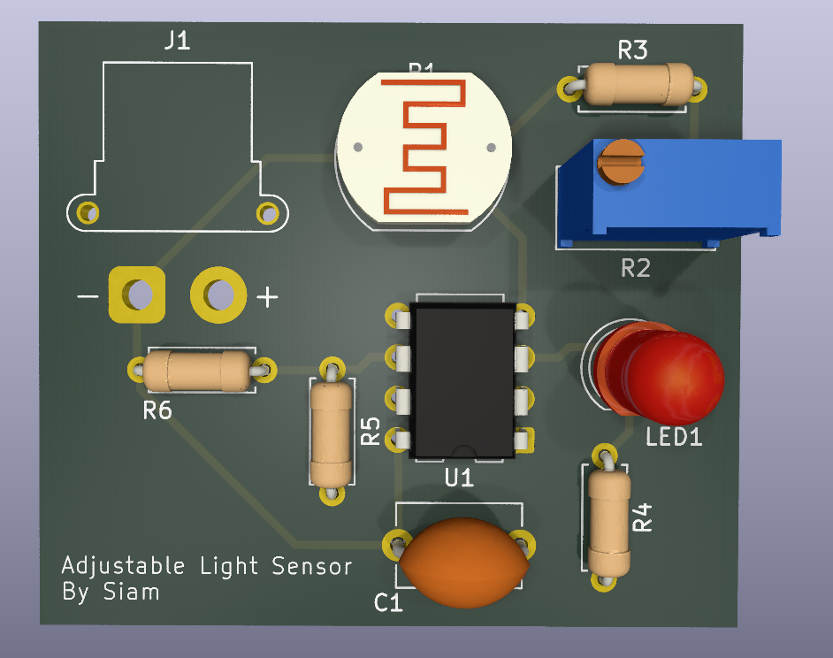
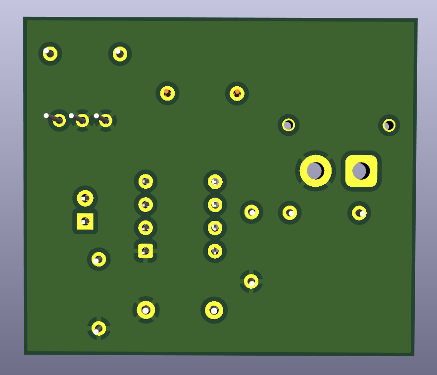
| Qty | Value | Footprint | References |
|---|---|---|---|
| 4 | R | Resistor_THT:R_Axial_DIN0207_L6.3mm_D2.5mm_P7.62mm_Horizontal | R3, R4, R5, R6 |
| 1 | 100n | Capacitor_THT:C_Disc_D7.5mm_W5.0mm_P7.50mm | C1 |
| 1 | Conn_01x02_Pin | Connector_AMASS:AMASS_XT30PW-F_1x02_P2.50mm_Horizontal | J1 |
| 1 | LDR03 | OptoDevice:R_LDR_10x8.5mm_P7.6mm_Vertical | R1 |
| 1 | LED | LED_THT:LED_D5.0mm | LED1 |
| 1 | NE555P | Package_DIP:DIP-8_W7.62mm | U1 |
| 1 | R_Potentiometer | Potentiometer_THT:Potentiometer_Bourns_3296W_Vertical | R2 |
It measures 43 × 37 mm and has 2 copper layers, 1.6 mm thick.
10 parts, built around the NE555P. The full list of its parts is on this page, with links to each part's symbol and footprint where PCBKit's library has them.
From the siamuwu/PCB_adjustable_light_sensor repository on GitHub, at the commit this page was made from: the board is EEEDay.kicad_pcb and its schematic EEEDay.kicad_sch. PCBKit opens the board in the browser, with nothing to install.
Its repository states no licence, so its author keeps all rights: ask siamuwu before reusing the design.
baldengineer/bit-preserve
Project for capturing vintage, classic, aka old computer schematics in KiCad.

The-Invent0r/8-bit-Computer-PCB
These are the KiCAD files for my 8-Bit Computer.

DarcyJProjects/touchtone555
An open-source DIY, NE555-based analogue synthesizer - play notes with a stylus


benjiaomodular/SynthCard
I designed this project with the help of PCBWay. You can get a copy of these cards through the PCBWay Shared Projects page.

fortinsylvain/MyCpu
Home brew CPU Hardware with 1-bit ALU implementation using 74LSxx, a micro-code and assembler coded in C#.

hackup/C128Diag
Replica of the Commodore C128 Diagnostic Test cartridge Assy No. 325093-01.