Skip to the content
2 layers60 × 40 mmANDgate, the printed circuit board in 3D

Logic Gates demonstration kit

Size
60 × 40 mm
Copper layers
2
Thickness
1.6 mm
Parts
12
Nets
8
Pads
42
Tracks, vias
73, 4
Pours
1
Routed
Yes
KiCad
KiCad 9.0 (file 20241229)
Created
13 Jan 2021
Updated
21 Nov 2025

Overview

ANDgate is an open-source printed circuit board by shurik179, from the shurik179/logicbits repository on GitHub, published under the MIT licence. It is a 2-layer board of 60 × 40 mm with 12 parts on 8 nets, routed with 73 tracks and 4 vias.

It is built around the 74LVC1G08Z. Its parts include 4 connectors, 3 resistors, 3 diodes, 1 capacitor and 1 IC.
Main components

1

README

README.md

Logic Gates Demonstration Kit

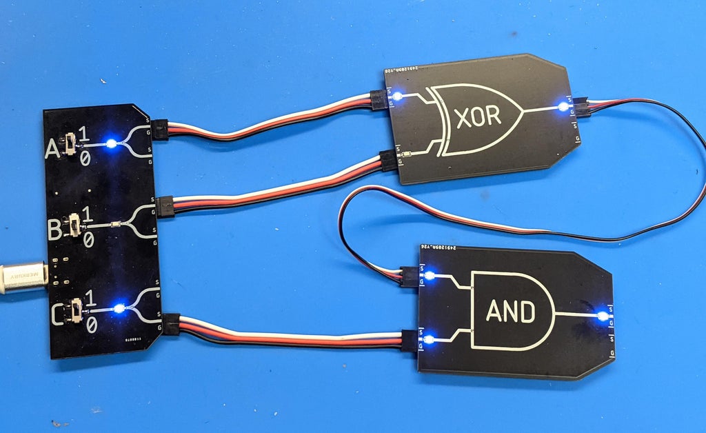
main image This directory contains files related to my Logic Gate Demonstraiton kit. This project is described in detail in my Instructable.

All files are released under MIT license; see LICENSE file in this directory for details.

Parts

12
QtyValueFootprintReferences
4Conn_01x03_MaleConnector_Molex:Molex_PicoBlade_53261-0371_1x03-1MP_P1.25mm_HorizontalJ1, J2, J3, J4
3330Resistor_SMD:R_0603_1608MetricR1, R2, R3
3LEDshurik-personal:LITE_ON_LTST_C230TBKT-LED_1206_3216Metric_ReverseMountD1, D2, D3
1100nFCapacitor_SMD:C_0603_1608MetricC1
174LVC1G08Package_TO_SOT_SMD:SOT-23-5U1

More from shurik179/logicbits

6
  • 2 layers40 × 96 mmINPUT, the printed circuit board in 3D

    INPUT

    shurik179/logicbits

    Logic Gates demonstration kit

    25 parts12MIT
  • 2 layers60 × 40 mmFlipflop, the printed circuit board in 3D

    Flipflop

    shurik179/logicbits

    Logic Gates demonstration kit

    20 parts12MIT
  • 2 layers60 × 40 mmORgate, the printed circuit board in 3D

    ORgate

    shurik179/logicbits

    Logic Gates demonstration kit

    12 parts12MIT
  • 2 layers60 × 40 mmXORgate, the printed circuit board in 3D

    XORgate

    shurik179/logicbits

    Logic Gates demonstration kit

    12 parts12MIT
  • 2 layers60 × 40 mmXORgate, the printed circuit board in 3D

    XORgate

    shurik179/logicbits

    Logic Gates demonstration kit

    12 parts12MIT
  • 2 layers60 × 40 mmNOTgate, the printed circuit board in 3D

    NOTgate

    shurik179/logicbits

    Logic Gates demonstration kit

    9 parts12MIT

Similar boards

  • 6 layers121 × 83 mmPS2 79004 Rev 0 4, the printed circuit board in 3D

    PS2 79004 Rev 0 4

    tschicki/PS2-Portable

    A custom designed PS2 Portable

    770 parts207MIT
  • 4 layers100 × 100 mmPCBA OCTV, the printed circuit board in 3D

    PCBA OCTV

    intechstudio/grid-hardware

    403 parts59GPL-3.0
  • 6 layers50 × 75 mmGmm, the printed circuit board in 3D

    Gmm

    GMM-7550/gmm7550-hardware

    CologneChip GateMate FPGA Module: GMM-7550

    252 parts36
  • 2 layers99 × 69 mmMSI001, the printed circuit board in 3D

    MSI001

    ATmega8/kiterf

    Release KiteRF is a SDR system with K210 & FPGA & ESP32 as its core controller, which make SDR more intelligent, portable and cheap.

    170 parts25MIT
  • 4 layers152.4 × 77.4 mmAppletini board, the printed circuit board in 3D

    Appletini board

    jtflanagan/AppleTini

    Teeny 4.1-based multifunctional Apple II peripheral card

    42 parts17BSD-2-Clause
  • 4 layers250.4 × 131 mmPanel-16, the printed circuit board in 3D

    Panel-16

    geezacoleman/owl-driver-board

    Development of a board that receives GPIO input and allows on/off control of connected solenoids.

    939 parts14MIT
  • 4 layers165 × 142.5 mmTestboard, the printed circuit board in 3D

    Testboard

    anthonydotmoe/68040pc

    A general purpose computer platform for retrocomputing enthusiasts

    175 parts9

Questions

How big is the ANDgate PCB?

It measures 60 × 40 mm and has 2 copper layers, 1.6 mm thick.

What parts does the ANDgate use?

12 parts, built around the 74LVC1G08Z. The full list of its parts is on this page, with links to each part's symbol and footprint where PCBKit's library has them.

Where can I download the ANDgate KiCad files?

From the shurik179/logicbits repository on GitHub, at the commit this page was made from: the board is V2/ANDgate/ANDgate.kicad_pcb and its schematic V2/ANDgate/ANDgate.kicad_sch. PCBKit opens the board in the browser, with nothing to install.

Can I use the ANDgate design in my own project?

Its repository publishes it under the MIT licence: you may reuse it on that licence's terms (keep the author's notice, and for a copyleft licence share your changes alike).