

2 layers181 × 97 mm
OpenDeck r3.1.2
shanteacontrols/OpenDeck
A platform for building interactive control and sensing devices using MIDI and OSC built with Zephyr RTOS.
262 parts960Apache-2.0

 shubham0x13/74hc165-module
A compact, daisy-chainable breakout module for the 74HC165 8-bit shift register.
74hc165-module is an open-source printed circuit board by shubham0x13, from the shubham0x13/74hc165-module repository on GitHub, published under the CERN-OHL-S-2.0 licence. It is a 2-layer board of 35 × 35 mm with 20 parts on 19 nets, routed with 83 tracks and 28 vias.
It is built around the 74HC165D. Its parts include 9 resistors, 4 connectors, 1 capacitor and 1 IC. It belongs with the interfaces and adapters and retro computing and games boards of this library.

A simple, compact, daisy-chainable breakout module based on the 74HC165 8-bit parallel-in/serial-out shift register. It allows you to add digital inputs to any microcontroller in multiples of 8, using only 3 GPIO pins plus power and ground.
[!NOTE] Revision History: Rev 2.0 is the first published release. The unpublished Rev 1.0 had a mirrored input header—while it worked standalone, daisy-chaining with a standard straight-through JST cable would short
VCCtoGND. Both headers now share the exact same pin order for safe, plug-and-play chaining. Rev 2.0 also changes theDINtermination from a pull-down to a pull-up to align with the default unpressed state of the input pins.
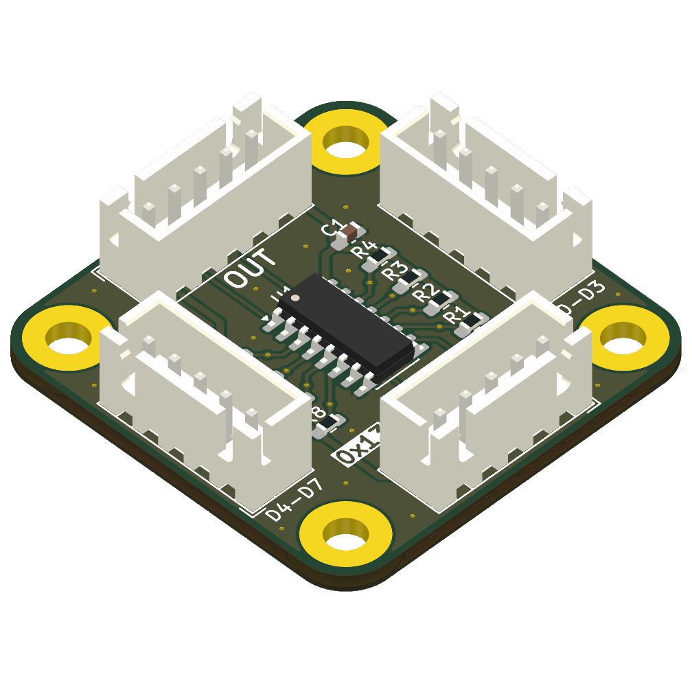
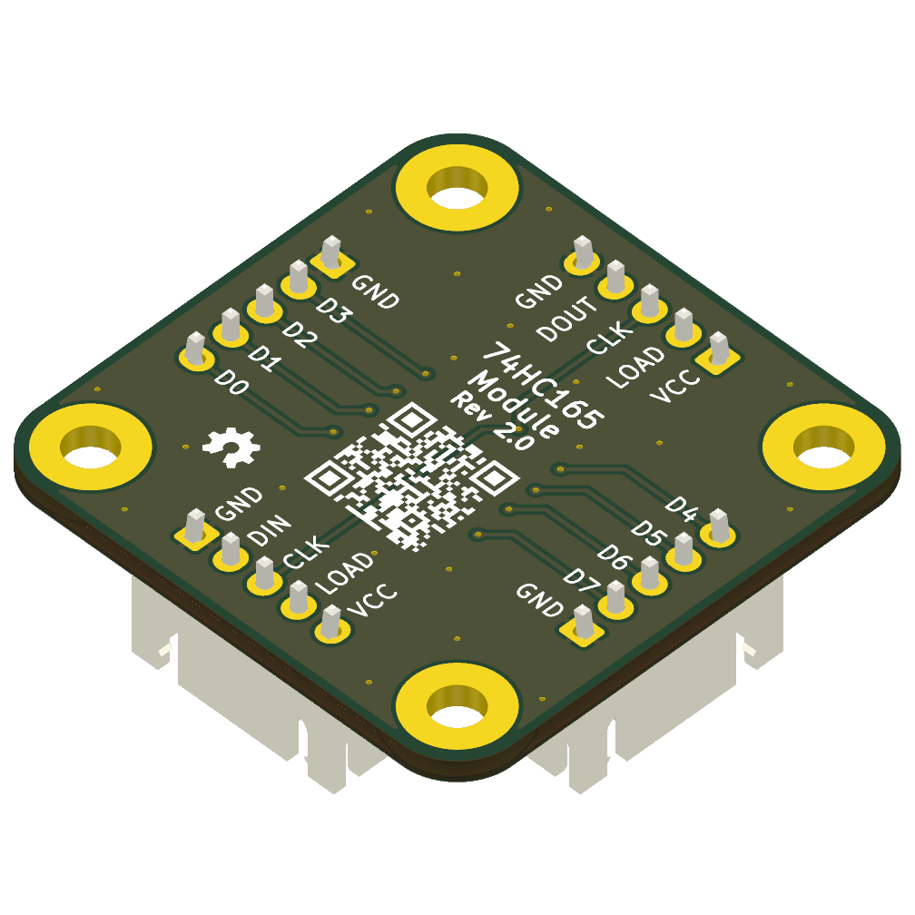
CLK, LOAD, VCC, and GND lines.DIN (to ensure that if the MCU reads more bits than are physically connected, the floating/ghost values default to 1, matching the unpressed state of the buttons), and a 100 nF decoupling capacitor.shiftIn), CircuitPython (adafruit_74hc165), and other platforms.Both 5-pin headers share the same pin layout:
DIN on J1, DOUT on J2)Wiring Guide:
[!NOTE] Inputs have hardware pull-ups (active-low). Wire your switches directly between
DxandGND. The MCU will read1(HIGH) when open, and0(LOW) when pressed.
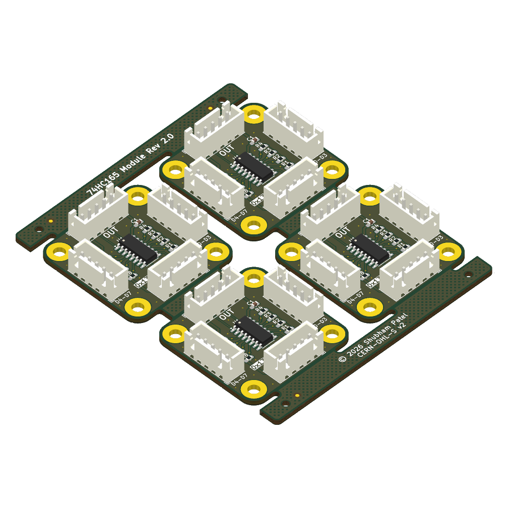
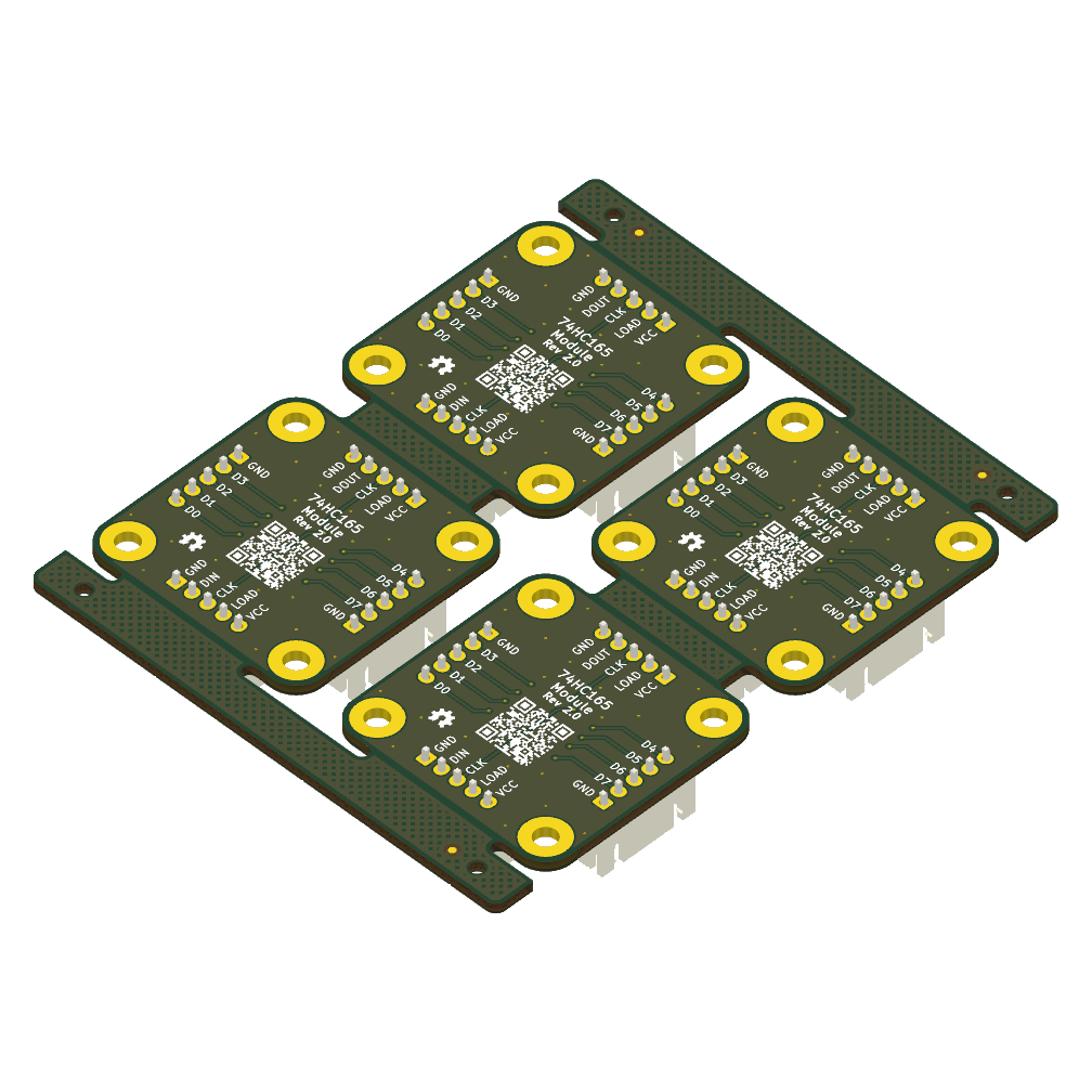
Ready-to-order fabrication files are available in the Releases tab. Each release includes:
.zip files (Single board & 4-board panel)[!IMPORTANT] The 4-board panel (75 × 91 mm) is generated via KiKit and outputs V-score/cut lines on the
User.Commentslayer by default. When ordering the panel, ensure this layer is included in your Gerbers and explicitly request V-scoring in your order notes.
To easily regenerate artifacts after modifying the PCB, a justfile is provided. It uses the KiCad CLI, KiKit, and InteractiveHtmlBom to generate the panel layout, Gerbers, STEP model, BOMs, schematic PDF, and 3D renders.
Requirements:
kicad-cli must be available in PATH)sh.exe for commands like rm and mkdir).Usage:
The build system is self-documenting. Run just from the repository root to see a list of all available commands and what they do.
# See all available build commands
justThis project is open-source hardware licensed under the CERN-OHL-S v2. See LICENSE for details.
| Qty | Value | Footprint | References |
|---|---|---|---|
| 8 | 10K | Resistor_SMD:R_0603_1608Metric_Pad0.98x0.95mm_HandSolder | R1, R2, R3, R4, R5, R6, R7, R8 |
| 4 | Conn_01x05 | Connector_JST:JST_XH_B5B-XH-A_1x05_P2.50mm_Vertical | J1, J2, J3, J4 |
| 4 | M3 | MountingHole:MountingHole_3.2mm_M3_Pad | MH1, MH2, MH3, MH4 |
| 1 | 100K | Resistor_SMD:R_0603_1608Metric_Pad0.98x0.95mm_HandSolder | R9 |
| 1 | 100nF | Capacitor_SMD:C_0603_1608Metric_Pad1.08x0.95mm_HandSolder | C1 |
| 1 | 74HC165 | Package_SO:SOIC-16_3.9x9.9mm_P1.27mm | U1 |
The 19 most common of 20 parts.
shanteacontrols/OpenDeck
A platform for building interactive control and sensing devices using MIDI and OSC built with Zephyr RTOS.

slu4coder/Minimal-64x4-Home-Computer
My DIY TTL home computer with VGA and PS/2 and 4x the processing power of a Commodore C64 or Apple II.

slu4coder/Minimal-UART-Computer-1-2
Legacy: Version 1 and 2 of my TTL-only CPU featuring UART I/O, an expansion port, 512KB SSD at up to 10MHz clock speed


westlicht/performer-hardware
PER|FORMER Eurorack Sequencer - Hardware Design Files

slu4coder/Minimal-64-Home-Computer
Legacy: Full TTL-only home computer with VGA and PS/2 and twice the processing power of a Commodore 64


It measures 35 × 35 mm and has 2 copper layers, 1.6 mm thick.
20 parts, built around the 74HC165D. The full list of its parts is on this page, with links to each part's symbol and footprint where PCBKit's library has them.
From the shubham0x13/74hc165-module repository on GitHub, at the commit this page was made from: the board is 74hc165-module.kicad_pcb and its schematic 74hc165-module.kicad_sch. PCBKit opens the board in the browser, with nothing to install.
Its repository publishes it under the CERN-OHL-S-2.0 licence: you may reuse it on that licence's terms (keep the author's notice, and for a copyleft licence share your changes alike).