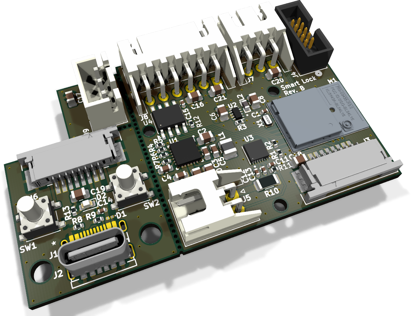
Smart lock is an open-source printed circuit board by shmuelzon, from the shmuelzon/lowkey repository on GitHub. It is a 4-layer board of 58.5 × 36 mm with 64 parts on 83 nets, routed with 323 tracks and 193 vias.
It is built around the DRV8871DDARQ1, MAX17205G+00E and DF2B7ASL,L3F. Its parts include 21 capacitors, 13 resistors, 9 connectors, 6 ICs and 2 diodes.
A battery-powered smart lock controller for a motorised deadbolt, built on the
Nordic nRF54L15 with the nRF Connect SDK.
It speaks Matter over Thread and a custom BLE GATT service at the same
time, on one Bluetooth controller. The two are not alternatives selected at
build time - they run concurrently, each with its own advertising set and its
own Bluetooth identity, so the lock stays controllable over BLE when the Thread
mesh or the Matter controller is down, and its BLE bonds survive Matter
commissioning and Matter factory resets.
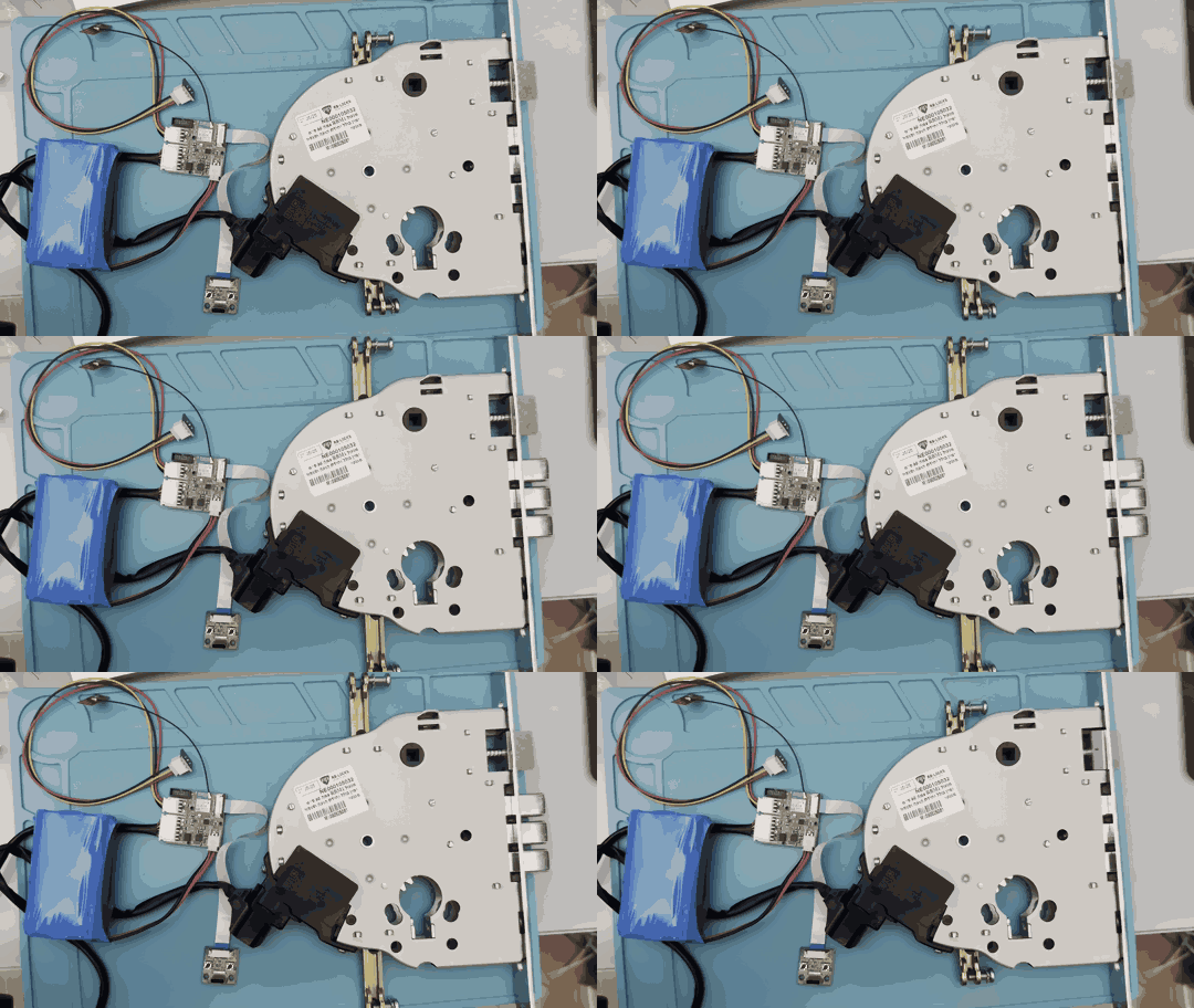
On the bench
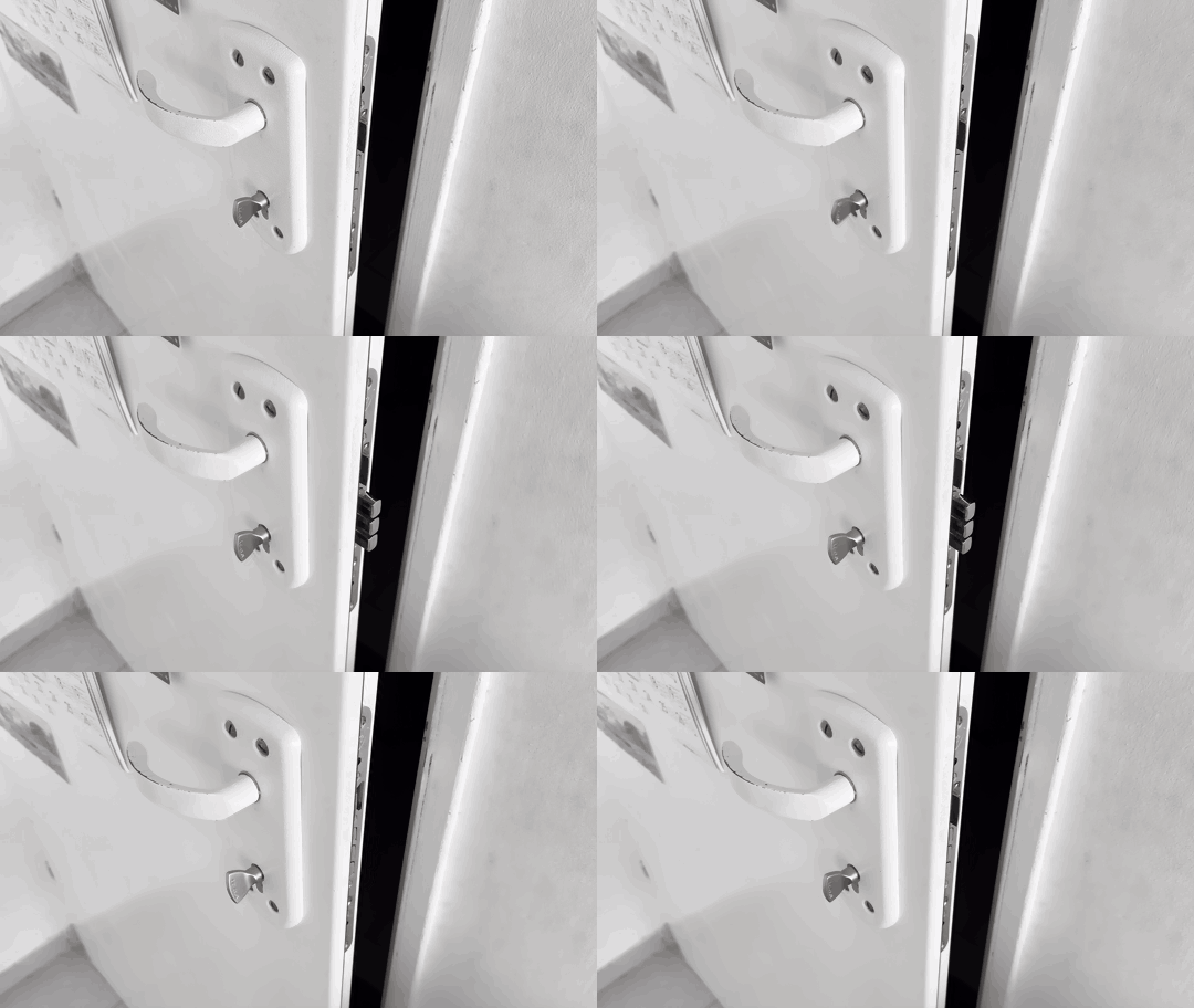
Installed in a door
Features
Three distinct actions, matching what a mortise deadbolt can actually do:
lock, unbolt (retract the bolt, spring latch still holds the door), and open
(retract the bolt and hold the latch back so the door can be pushed).
These map to the Matter LockDoor, UnboltDoor and UnlockDoor commands.
Position tracked from the bolt, not from the motor. The lock body's two
magnetic end-stop sensors are monitored continuously, so operating the lock
with a physical key updates the reported state exactly like a remote command
does.
Jam detection - the motor stops and the lock reports jammed, with a Matter
DoorLockAlarm event, if an end-stop is not reached in time.
Door position sensor, reported as a Matter DoorStateChange.
Battery monitoring with a MAX17205 ModelGauge m5 fuel gauge, plus charger
connected/complete status.
Firmware update over both Bluetooth SMP (MCUmgr) and Matter OTA, sharing
one MCUboot slot pair with LZMA-compressed images.
Per-device provisioning - serial number, BLE pairing passkey, Matter
discriminator and SPAKE2+ verifier in a dedicated flash partition that OTA
never touches.
Task watchdog with a channel per critical thread.
Hardware
Lock body
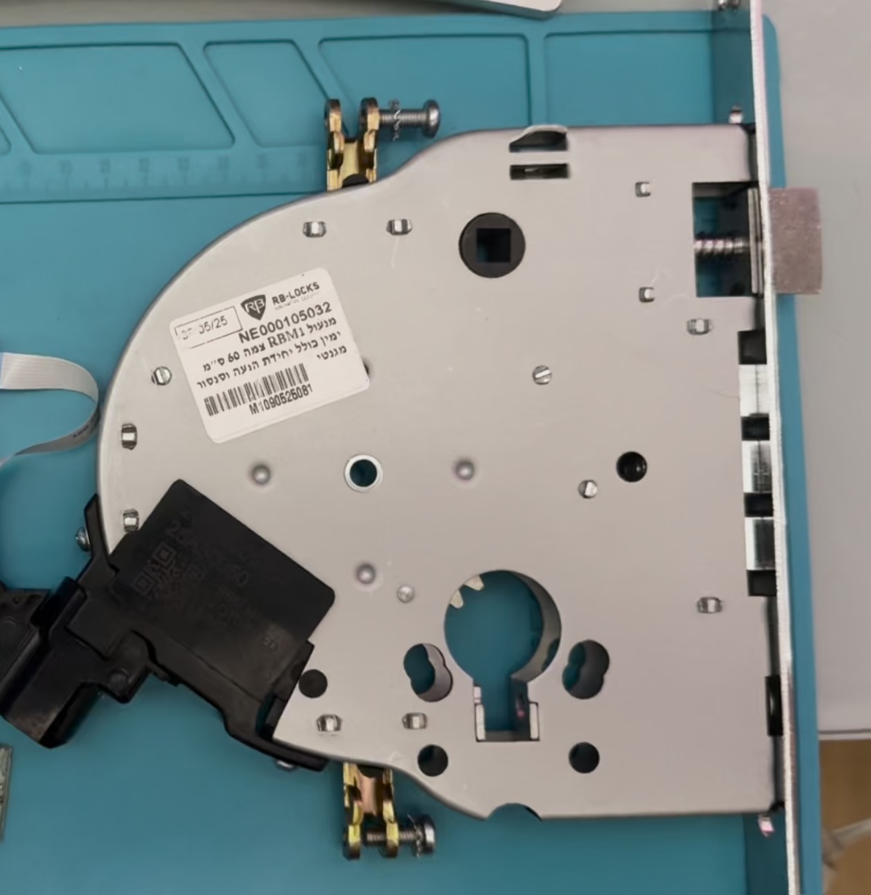
The mechanism is a Rav Bariach RBM1, a motorised mortise lock. The motor
unit and the magnetic sensors for the two bolt end-stops come built into the
body. The controller only has to drive the motor and read the sensors, all
through one 6-pin harness:
One KiCad project holds three boards, panelised with mouse bites:
Main board: the Ezurio BL54L15 module (nRF54L15, with an MHF4
connector for an external antenna, so there is no RF switch to manage),
charger, regulator, fuel gauge, motor driver, and connectors for the
battery, the lock harness, the door sensor and SWD.
UI board: the two keys, the status LED and the USB-C charging port. It
connects to the main board over an 8-way FFC.
Door sensor board: a single Hall sensor with a 3-pin JST XH cable to
the main board. It also carries an alternative footprint for a Coto RR123
magnetoresistive sensor, which is not fitted.
Power comes from a 2S Li-ion pack, two 18650 or 21700 cells in series, on a
2-pin JST XH connector. See Battery life for what to expect
from each.
Part
Role
Ezurio 453-00044R (BL54L15)
nRF54L15 module
TE 2344656-6
External 2.4 GHz antenna
TI BQ25886
2S battery charger from USB-C, 1.03 A charge current (ITERM 103 mA)
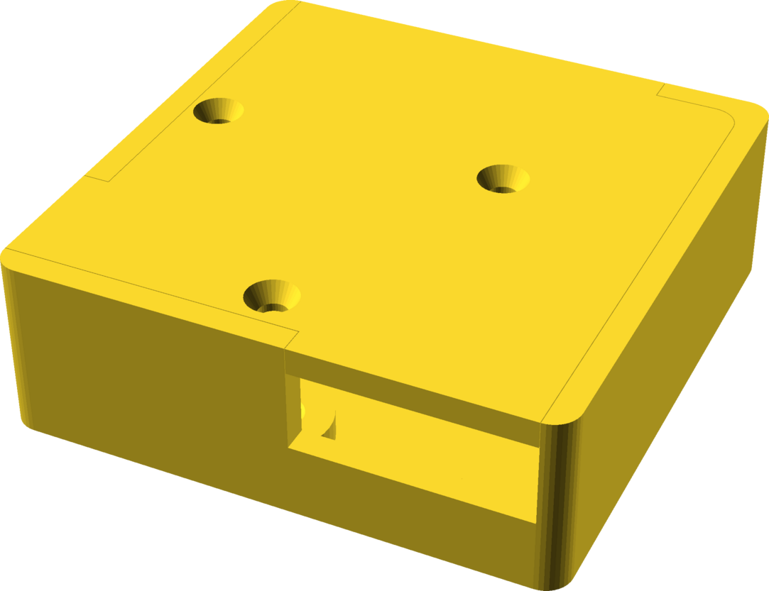
Controller: a 42 × 42 × 13.8 mm box for the main board. It has openings
for the lock harness, the battery lead and the UI cable, and closes with
three M2 countersunk screws into heat-set inserts.
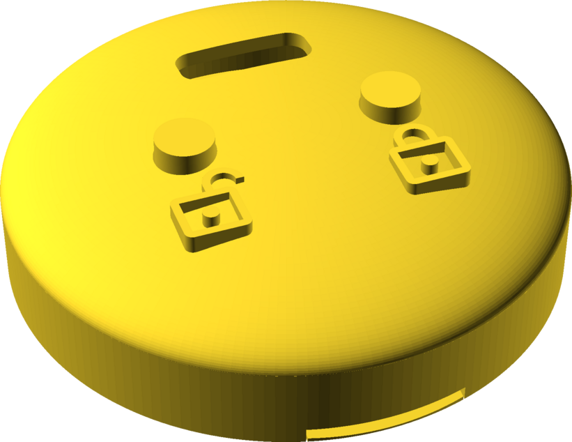
UI: a Ø34 mm dome for the UI board, with lock and unlock icons embossed
beside the two key caps. It closes with two M2 countersunk screws into
heat-set inserts.
Both enclosures use 3.45 mm outer-diameter M2 inserts. Each STL holds every
part of its enclosure (base, lid and, for the UI, the key caps) as separate
bodies; split them into objects in your slicer. The show_* variables at the
top of each .scad export a single part.
Regenerating the outputs
The PDF, the renders and the STLs are committed so they can be viewed on
GitHub. After changing a source, regenerate them with:
sh
make -C hardware          # everything
make -C hardware pcb      # schematic PDF and board render (KiCad 10)
make -C hardware 3d       # STLs and enclosure renders (OpenSCAD)
The Makefile finds kicad-cli, openscad and ImageMagick's magick in
PATH, in their usual macOS locations, and under C:\Program Files from WSL or
Git Bash. Point it at a tool anywhere else with
make KICAD_CLI=... OPENSCAD=... MAGICK=.... ImageMagick is optional: it gives
the renders a transparent background and trims them to the model.
OpenSCAD must be a development snapshot with the Manifold backend. The 2021.01
release only has CGAL, which rejects the imported PCB meshes and silently drops
their cutouts, so the Makefile refuses to use it.
Repository layout
text
boards/shmuelzon/lowkey/   Board definition (revisions A and B) and its DTS bindings
src/                       Application
  ├─ lock_manager.c        Motor drive and the bolt/latch state machine
  ├─ door_monitor.c        Door position sensor
  ├─ battery_manager.c     MAX17205 fuel gauge and charger status
  ├─ ui.c                  Keys and status LED
  ├─ gpio_input.c          Interrupt-driven GPIO inputs, optionally debounced
  ├─ watchdog.c            Task watchdog
  ├─ radio.c               Fans the radio API out to the backends below
  ├─ ble/                  Custom GATT services (CONFIG_LOCK_RADIO_BLE)
  └─ matter/               Clusters and ZAP data model (CONFIG_LOCK_RADIO_MATTER)
scripts/                   Factory-data generation, device label, Intel HEX padding
sysbuild/mcuboot/          MCUboot configuration
pm_static.yml              Flash partition layout
hardware/                  Makefile that regenerates the outputs below
  ├─ pcb/                  KiCad project, schematic PDF and board render
  └─ 3d/                   OpenSCAD enclosures, STLs and renders
docs/                      README media
Getting started
Built against nRF Connect SDK v3.2.4.
sh
# Toolchain and SDK
curl -o ~/bin/nrfutil "https://files.nordicsemi.com/ui/api/v1/download?repoKey=swtools&path=external/nrfutil/executables/x86_64-unknown-linux-gnu/nrfutil&isNativeBrowsing=false"
chmod +x ~/bin/nrfutil
nrfutil install sdk-manager toolchain-manager
nrfutil sdk-manager install v3.2.4
cd ~/ncs/v3.2.4 && west update
# Per-shell environment (needed for west build and west zap-generate)
SDK_VERSION=v3.2.4
source ~/ncs/$SDK_VERSION/zephyr/zephyr-env.sh
eval $(nrfutil toolchain-manager env --ncs-version $SDK_VERSION --as-script)# Python packages used by the provisioning script
pip install cbor2 intelhex jsonschema pillow pyyaml qrcode
Building
The board has two PCB revisions, selected with the @ suffix. They differ only
in the motor driver: rev A (DRV8837) has an nSLEEP enable pin, rev B
(DRV8871) sleeps on its own and omits it.
sh
# Product build: both radios, release
west build --pristine -b lowkey@B/nrf54l15/cpuapp -- -DBOARD_ROOT="$PWD"# Debug: RTT console and logging
west build --pristine -b lowkey@B/nrf54l15/cpuapp -- -DBOARD_ROOT="$PWD" \
-DEXTRA_CONF_FILE="overlay-debug.conf"# One radio only
west build --pristine -b lowkey@B/nrf54l15/cpuapp -d build-ble -- \
-DBOARD_ROOT="$PWD" -DCONFIG_LOCK_RADIO_MATTER=n -DSB_CONFIG_MATTER=n
west build --pristine -b lowkey@B/nrf54l15/cpuapp -d build-matter -- \
-DBOARD_ROOT="$PWD" -DCONFIG_LOCK_RADIO_BLE=n
Both radios are on by default. There are no prj_*.conf protocol fragments -
CONFIG_LOCK_RADIO_BLE and CONFIG_LOCK_RADIO_MATTER in the project Kconfig
carry all protocol-specific configuration, so a build is described by the board
plus those two switches.
Approximate image sizes (of the 810 KiB application slot):
Build
Flash
RAM
Both radios
78 %
79 %
Both radios, debug
90 %
80 %
Matter only
72 %
68 %
BLE only
24 %
28 %
Two things that will bite you:
Use -DEXTRA_CONF_FILE, not -DOVERLAY_CONFIG. Under sysbuild the latter
is applied to every image, including MCUboot, where it breaks image signing
with a confusing @PM_MCUBOOT_PRIMARY_SIZE@ is not a valid integer.
-DSB_CONFIG_MATTER=n is separate from -DCONFIG_LOCK_RADIO_MATTER=n.
Sysbuild's Kconfig cannot see the application's, so a Matter-less build still
emits a matter.ota artifact unless you pass both.
Changing the Matter data model
The files under src/matter/zap-generated/ are generated from
src/matter/lock.zap:
sh
west zap-gui        # or edit the JSON directly
west zap-generate
If you add or remove a cluster, force a CMake reconfigure before rebuilding
(touch CMakeLists.txt, or build --pristine). Cluster-to-source selection
happens at configure time only, so an incremental build fails at link with
something like undefined reference to MatterPowerSourcePluginServerInitCallback.
Flashing
A build produces build/merged.hex (MCUboot + signed application) for SWD,
build/dfu_application.zip for MCUmgr, and build/matter.ota for Matter OTA.
sh
./scripts/pad_hex.py build/merged.hex
west flash
Pad the HEX file first
scripts/pad_hex.py pads the last data record of an Intel HEX file to 16
bytes with 0xFF. This works around an OpenOCD nRF5 driver issue where the
RRAMC write buffer is not flushed for a trailing partial block, which
silently corrupts the ED25519 signature at the end of the MCUboot image -
the device then refuses to boot for no visible reason.
This affects on-board debuggers driven through OpenOCD, including the one on
the Seeed XIAO nRF54L15. Run it before every flash, on merged.hex and on
factory_data.hex alike. It is idempotent.
Provisioning
Every device needs its own factory data: a serial number, a BLE pairing
passkey, and (for Matter) a discriminator and SPAKE2+ verifier. These live in a
4 KiB factory_data partition that firmware updates never overwrite.
Every argument has a default and the per-device secrets are drawn randomly when
not given, so the command above is the whole flow for a development unit. It
writes five files:
File
Contents
factory_data.hex
The partition image, at the offset and size read from pm_static.yml
factory_data.json
Every generated value except the Matter passcode
factory_data.txt
Matter manual pairing code and QR payload
factory_data.png
The same QR code as an image
factory_data.sticker.png
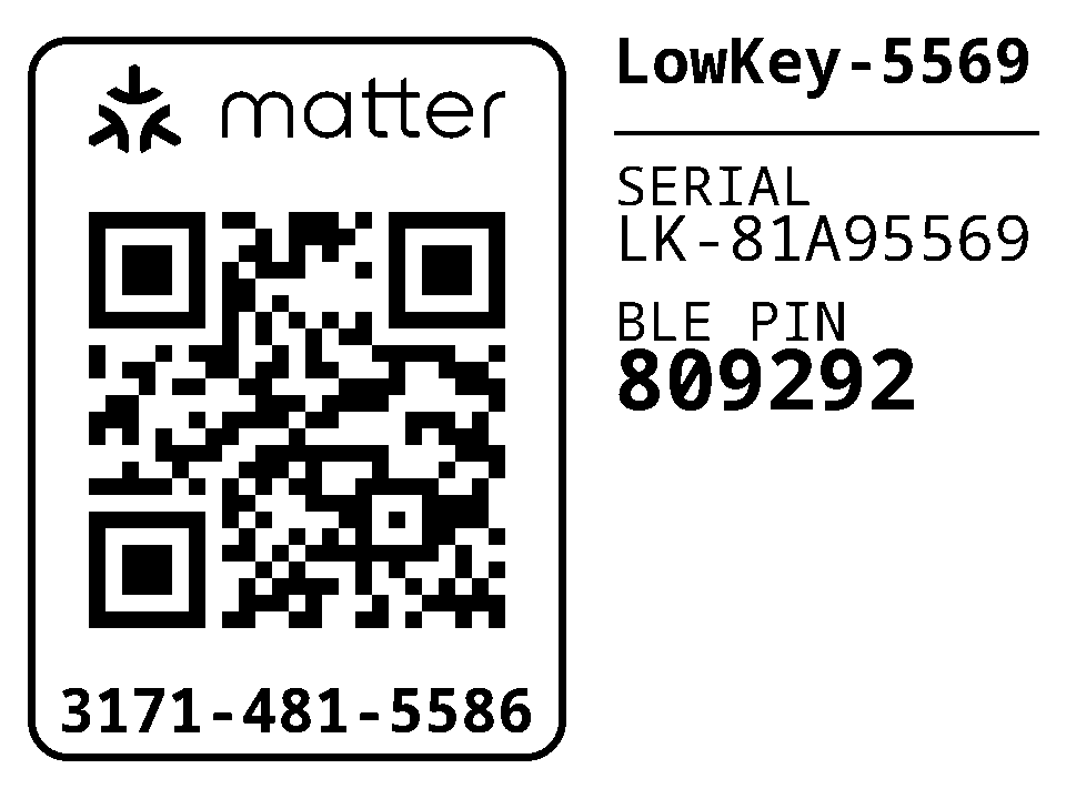
A printable device label: Matter QR and pairing code, BLE name, serial number and BLE passkey
Archive the .json and .txt per device - together they are the only record.
Use --no-matter for a BLE-only build, and --help for the full set of
overrides (--sn, --ble_passkey, --passcode, --discriminator,
--battery_capacity_mah, the DAC/PAI certificate paths, --sticker-size,
--no-sticker, …). To reprint the label for a unit provisioned earlier, run
python3 scripts/generate_sticker.py factory_data.
An example label. Its codes were randomly generated and belong to no device.
The onboarding codes printed at boot are wrong
The Matter passcode is deliberately not stored on the device - only the
one-way SPAKE2+ verifier is, so reading out the flash does not reveal it. The
firmware therefore cannot rebuild its own onboarding payload and falls back to
Matter's example passcode, making the Manual pairing code and SetupQRCode
lines in its boot log useless:
text
[DL]  Setup Pin Code (0 for UNKNOWN/ERROR): 0
[SVR]*** Using default EXAMPLE passcode 20202021 ***
Commission with the codes in factory_data.txt. Pass --include-passcode
if you would rather store the passcode and trust the boot log, at the cost of
it being readable out of flash.
Before shipping anything
The stock configuration is a development configuration:
Attestation certificates default to the Matter SDK's test DAC/PAI for
test VID/PID 0xFFF1/0x8000. Production devices need certificates from a
real PAA. The script warns if you change the VID/PID without supplying them.
Images are signed with MCUboot's public development key, so anyone can
produce an image this bootloader accepts. Generate your own and point the
build at it - this cannot be changed after units ship, because MCUboot is the
immutable first-stage bootloader:
sh
On nRF54L15, SB_CONFIG_BOOT_SIGNATURE_USING_KMU can hold the public key in
hardware instead of bootloader flash.
Using the lock
Keys and LED
The key layout is chosen at build time from devicetree, by whether a key1
alias exists:
Short press
Long press
key0
Lock
Factory reset (10 s)
key1
Unbolt
Open for commissioning / pairing (1.5 s)
On a board with only key0, a short press opens the discovery window and the
long press is still factory reset - both are mandatory in every layout, and the
build fails if either is unassigned. Factory reset sits on the lock key
deliberately: the key someone leans on when the door will not open is the unlock
one, and ten seconds of that should not wipe the fabric.
LED
Meaning
Fast blink (100 ms)
Factory reset fires in 3 seconds - release to abort
Slow blink (500 ms)
Discoverable, identifying, or charging
Solid
Charge complete
Off
Idle
One press of the discovery key opens an onboarding window on both radios and
lets your app pick; the first to complete closes the other. To pair a BLE client
and commission to Matter, press it twice, once per path.
Matter
Endpoint 1 exposes Door Lock (with the Unbolting and DoorPositionSensor
features), Power Source, Identify and ICD Management. There is no
PIN/RFID/user support - the lock has no keypad, and those cluster features are
deliberately absent from the data model rather than stubbed.
The device is a Thread sleepy end device. Inbound latency is bounded by the
ICD poll interval (500 ms idle); outbound reporting of bolt and door changes is
immediate.
The lock advertises as LowKey-XXXX, where XXXX is the last four characters
of the serial number, so the name on the label matches without reading anything
off the device.
Porting to another board
The application depends only on the devicetree contract below - no board-specific
code. Everything is reached through aliases except three node labels.
Required aliases
Alias
Direction
Expected wiring
led0
Output
Status LED
key0
Input
Push button, active low with pull-up
key1
Input
Second button. Optional - its presence changes the key layout
lock-sensor
Input
Active when the bolt is fully extended
unlock-sensor
Input
Active when the bolt is fully retracted
door-sensor
Input
Active when the door is closed
chg-power-good
Input
Active when input power is present
chg-stat
Input
Active while charging; inactive means complete
Every input is configured for both-edge interrupts, so all of them must be
on interrupt-capable pins. On the nRF54L15 that means P0 or P1 - P2 has no
GPIOTE peripheral.
Required node labels
Label
Notes
motor_driver
compatible = "lowkey,motor-driver"; in1-gpios and in2-gpios required, nsleep-gpios optional
Referenced by label, not by the watchdog0 alias, and must be status = "okay"
Plus a factory_data partition, supplied by Partition Manager from
pm_static.yml.
Board-level requirements
&cpuapp_rram { reg = <0x0 DT_SIZE_K(1524)>; } in every image, including
MCUboot (sysbuild/mcuboot/app.overlay). pm_static.yml spans the full
1524 KiB by reclaiming the unused FLPR coprocessor's RRAM; miss this in any
one image and the layout overflows flash_primary and the build fails.
&uicr { nfct-pins-as-gpios; } if you reuse P1.02/P1.03. These power up in
NFC mode, and the NFCT pad network holds them low, overriding the GPIO
pull-ups - the keys read stuck-low. Disabling the nfct node is not enough.
Disable uart21 in MCUboot on any board that enables it. If the UARTE
driver initialises during MCUboot, its pins latch as UART-TX-idle-high and
that hardware state survives into the application, overriding GPIO output.
Keep application RAM low if you care about idle current: power_down_unused_ram()
powers down whole 32 KiB SRAM sections above the image, so every 32 KiB the
image gives back is one more section switched off.
Tunables
All in the project Kconfig, prefixed CONFIG_LOCK_:
Symbol
Default
Purpose
MOTOR_TIMEOUT_MS
3000
End-stop not reached in this time ⇒ jammed
MOTOR_BRAKE_US
2000
Dynamic braking before coasting and before reversing
BOLT_SEATING_MS
100
Extra drive after the lock end-stop, to seat the bolt
UNBOLT_SEATING_MS
0
Extra drive after the unlock end-stop
LATCH_RELEASE_MS
500
Extra drive on an open, to hold the latch back
BATTERY_POLL_INTERVAL_S
60
Fuel gauge polling
BUTTON_DEBOUNCE_MS
30
Mechanical key debounce
WATCHDOG_TIMEOUT_MS
30000
Task watchdog, per channel
WATCHDOG_FEED_MS
5000
Feed interval
DISCOVERY_TIMEOUT_S
180 / 60
Onboarding window (180 with Matter)
DISCOVERY_PRESS_MS
1500
Hold time for discovery
FACTORY_RESET_PRESS_MS
10000
Hold time for factory reset
BLE_TX_POWER_DBM
7
Applied at runtime over vendor HCI
Adapting to a different lock body
The mechanism needs, at minimum:
Two motor pins into an H-bridge (in1-gpios, in2-gpios), plus an
optional enable pin (nsleep-gpios) if the driver has one.
Two end-stop sensors telling the firmware when the bolt has reached each
extreme.
One door sensor (optional in practice - omit the Matter
DoorPositionSensor feature from lock.zap if you have none).
The H-bridge is driven as:
IN1
IN2
Effect
0
0
Coast (idle)
0
1
Drive toward locked
1
0
Drive toward unlocked
1
1
Brake
Swap in1-gpios and in2-gpios if your motor runs the wrong way.
Sensors are expected to be solid-state, active-low, with no pull-up - Hall
sensors with a push-pull output stage, where a pull-up would only waste current.
They are deliberately not debounced: they do not bounce, and any delay here
lands between the end-stop firing and the motor stopping, adding bolt travel.
Only the mechanical keys are debounced. If you use reed switches or another
bouncing sensor, pass a non-zero debounce to gpio_input_init() in
lock_manager.c and door_monitor.c.
Timing notes for a different mechanism:
LATCH_RELEASE_MSis the window during which the door can be pushed open.
The latch is spring-loaded and returns the instant the motor releases the cam,
so this is a usability number, not just a mechanical one.
UNBOLT_SEATING_MS defaults to 0 because on this lock the unbolt travel heads
toward the latch, so any extra drive starts releasing it. If your mechanism
is different, this is where extra retraction goes.
A Matter build refusesLATCH_RELEASE_MS=0 (a BUILD_ASSERT), because
lock.zap advertises the Door Lock Unbolting feature, which promises a
controller that UnlockDoor pulls the latch. Clear that feature bit from the
FeatureMap if your lock cannot.
Power
The design targets a multi-year battery life on a 2S pack. What the firmware
does for it:
vregmain in DCDC mode, and unused SRAM sections powered down at boot.
Thread MTD/sleepy end device, with the ICD intervals retuned - the NCS
defaults are self-defeating, because the fast poll interval is longer than the
active-mode duration, so the fast interval is unreachable and every round trip
of a multi-message exchange pays the full idle interval.
BLE advertising slows to a ~1 s interval once bonded.
The motor driver sleeps between operations, and the fuel gauge is polled once
a minute plus once after each completed operation.
Runtime device PM, so the I²C peripheral is suspended between transfers.
Battery life
Measured draw:
State
Current
Idle
70 µA
Motor running
200 mA, for about 1 s per lock or unlock
At around 40 lock/unlock cycles a day, a pack of two 3000 mAh 18650 cells in
series is expected to last about 1.3 years, and two 5000 mAh 21700 cells about
2.2 years.
Known limitations
The onboarding codes in the boot log are wrong unless you provision with
--include-passcode. See
above.
Partition boundaries are permanent. MCUboot is the immutable first-stage
bootloader with the slot offsets compiled into it, there is no NSIB s0/s1
pair, and serial recovery is off - it could not work anyway, since the board
enables no UART. Changing any address in pm_static.yml means reflashing over
SWD.
MCUboot is not write-protected at runtime.fprotect caps a protected
region at 62 KiB and the bootloader partition is 72 KiB, so enabling it would
make MCUboot halt at startup. Shrinking the partition below 62 KiB is the only
way to have both.
The Matter module is required even for a BLE-only build. The application
reads factory data with the SDK's FactoryDataParser.c, which lives in the
Matter module; it depends only on zcbor, so it links without the rest of the
stack, but the module has to be present.
The watchdog does not cover the Bluetooth RX thread. It has a channel for
the system workqueue and one for the Matter event loop.
It measures 58.5 × 36 mm and has 4 copper layers, 1.56 mm thick.
What parts does the Smart lock use?
64 parts, built around the DRV8871DDARQ1, MAX17205G+00E and DF2B7ASL,L3F. The full list of its parts is on this page, with links to each part's symbol and footprint where PCBKit's library has them.
Where can I download the Smart lock KiCad files?
From the shmuelzon/lowkey repository on GitHub, at the commit this page was made from: the board is hardware/pcb/smart-lock.kicad_pcb and its schematic hardware/pcb/debug_and_connectors.kicad_sch. PCBKit opens the board in the browser, with nothing to install.
Can I use the Smart lock design in my own project?
Its repository states no licence, so its author keeps all rights: ask shmuelzon before reusing the design.
A Robojackets robot (v2) built from scratch, featuring a custom 4-layer PCB, STM32-based (ARM Cortex-M3) firmware written in C (STM32CubeMX + CMake), and a 3D-printed chassis.


 shmuelzon/lowkey4