
2 layers100 × 50 mm
Conveyor belt pcb
lansidev/conveyor-belt
Miniature 3D printed conveyor belt for simulation and fun working with sensors, all controllable with Raspberry Pi
22 parts9MIT

 SharKingStudios/Starbie28
Half-Life Week 1 Example Project
Starbie is an open-source printed circuit board by SharKingStudios, from the SharKingStudios/Starbie repository on GitHub, published under the MIT licence. It is a 2-layer board of 96.6 × 82.8 mm with 11 parts on 25 nets, routed with 32 tracks and 0 vias.
It is built around the DHT11. Its parts include 2 ICs, 2 connectors, 2 switches and 1 resistor. It belongs with the ESP32 and RISC-V boards of this library.
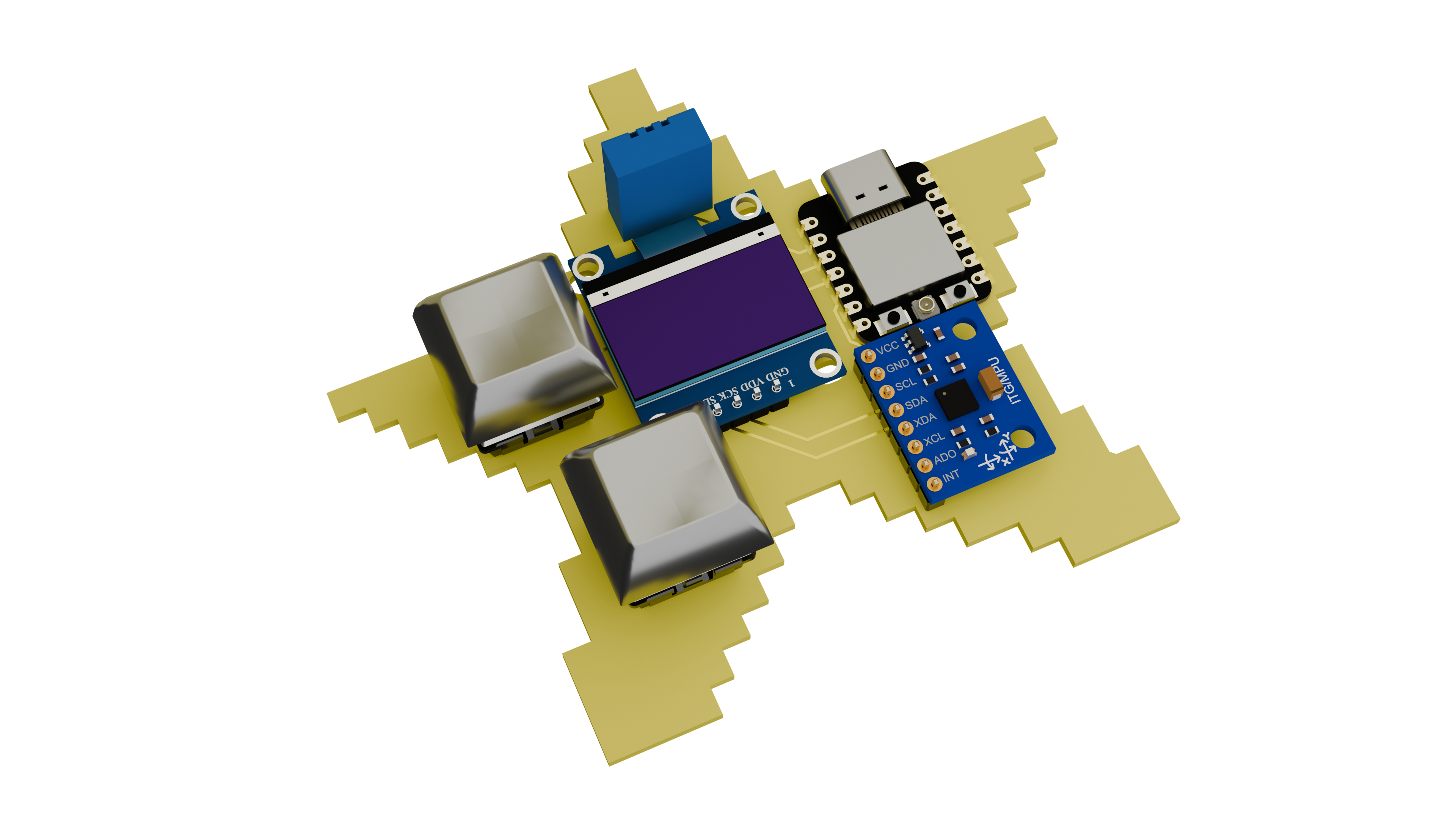
Starbie is a tiny motion-controlled digital pet: basically a desktop Tamagotchi with minimal gameplay buttons. Instead of pressing controls, you interact with it by physically moving the board.
Looking for the guide! You can find it here!
Starbie is designed to sit on your desk, show its personality on a small display, and react to how you handle it. Tilting, moving, and otherwise checking in on your pet are meant to be part of the experience.
The board includes a microcontroller, display, motion sensor, and environmental sensor in a compact PCB design. It is USB powered and built around beginner-friendly through-hole soldering for the add-on components.
This project was created to be the week 1 beginner tutorial for halflife!
The PCB design, renders, and an Arduino starter firmware are included here. The default program is a two-eye pet with a tilt-controlled radial menu, hidden stats, and a shake reaction.
Firmware/ contains one self-contained Arduino IDE sketch for the XIAO ESP32-C3. Builders customize pins, menu actions, starting values, and motion settings together at the top of the sketch. The folder also includes a draggable browser simulator. See the firmware README for setup notes.
PCB/ - KiCad source files and fabrication exportsRenders/ - front and back PCB rendersWeek 1 Guide.md - project guide materialFirmware/ - Arduino IDE starter sketch| Qty | Value | Footprint | References |
|---|---|---|---|
| 4 | LOGO | LOGO | G***, G***, G***, G*** |
| 2 | SW_Push | Button_Switch_Keyboard:SW_Cherry_MX_1.00u_PCB | SW1, SW2 |
| 1 | 10k | Resistor_THT:R_Axial_DIN0204_L3.6mm_D1.6mm_P7.62mm_Horizontal | R1 |
| 1 | Conn_01x04_Pin | Imported Parts:Display_128x64_096_I2C | J1 |
| 1 | Conn_01x08_Pin | Connector_PinHeader_2.54mm:PinHeader_1x08_P2.54mm_Vertical | J2 |
| 1 | DHT11 | Sensor:Aosong_DHT11_5.5x12.0_P2.54mm | U1 |
| 1 | XIAO-ESP32-C3-SMD | Imported Parts:XIAO-ESP32-C6-DIP | U2 |
It measures 96.6 × 82.8 mm and has 2 copper layers, 1.6 mm thick.
11 parts, built around the DHT11. The full list of its parts is on this page, with links to each part's symbol and footprint where PCBKit's library has them.
From the SharKingStudios/Starbie repository on GitHub, at the commit this page was made from: the board is PCB/Starbie.kicad_pcb and its schematic PCB/Starbie.kicad_sch. PCBKit opens the board in the browser, with nothing to install.
Its repository publishes it under the MIT licence: you may reuse it on that licence's terms (keep the author's notice, and for a copyleft licence share your changes alike).
lansidev/conveyor-belt
Miniature 3D printed conveyor belt for simulation and fun working with sensors, all controllable with Raspberry Pi


ebrithiljonas/OMG_PCB
All in One PCB for the OpenMQTTGateway Project

GeorgK/SniffingTrinket
A room climate monitor using the Adafruit Trinket Pro

bhaskar9980/Guardian
Guardian is an advanced, fully automated hydroponics system designed to optimize plant growth and maximize yield.

Twistx77/Firefly
Open WIFI-enabled RGB lamp with temperature, humidity, suspended air particles and eCO2 sensors.

unla-investigacion-desarrollo/ecosistema-iot
Antes de desarrollar el sistema final, realizamos una etapa de exploración donde investigamos y experimentamos con las siguientes tecnologías:

AvishkaVishwa/Microcontroller-Design-Project-Temperature-Monitoring-System
This project is a temperature display and alarm system designed for educational purposes as part of the IA 2209 - Microcontroller Laboratory course.