2 layers
Encoder
byrantech/laptop
anyon_e, a highly integrated, high end, open source laptop. Attempt the impossible.
7 parts4.3kMIT
 settinger/Birobot
(as in _Biro_ + _Robot_)
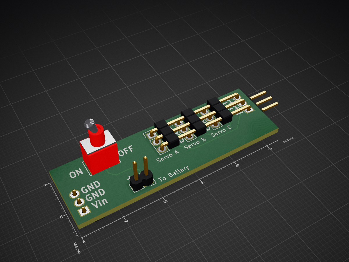
Penshield is an open-source printed circuit board by settinger, from the settinger/Birobot repository on GitHub, published under the BSD-3-Clause licence. It is a 2-layer board of 53.3 × 16.5 mm with 7 parts on 7 nets, routed with 46 tracks and 0 vias.
(as in Biro + Robot...the name is not finalized, let me know if you have a catchy suggestion)
Birobot is a delta-configuration pen plotter designed to be easy to build and easy to program. It can be programmed like a standard Arduino project, or you can control it by giving it a series of coordinates in an easy-to-read plain text format.
This project is developed and maintained by Sam Ettinger, an associate at Robot Sapience, Ltd., Hong Kong. This documentation is, like the project, in its infancy. Please report any questions or problems you encounter!
The Arduino code can be uploaded to Birobot from any computer with the Arduino IDE. To use the plaintext-coordinate uploader, some additional files are required.
Birobot.ino, helperfxn.ino, constants.ino, and path.ino. Make sure the capitalization of the folder matches the capitalization of Birobot.ino (the rest don't matter).constants.ino contains a list of variables that correspond to physical dimensions of Birobot. These should be as accurate as possible for smooth, linear motion of the end effector.path.ino contains a list of waypoints that Birobot will visit in succession. These can be edited by hand, or by using upload.bat (see below).upload.bat to the same folder as the Arduino project.path.txt in the same folder as upload.bat. Fill it with coordinates (one coordinate per line). Take a look at the demo files for examples.upload.bat. This will look for a file called path.txt, convert the plaintext coordinates to something Arduino-readable, and upload it to the Arduino controlling Birobot.The Birobot design is still in progress. You can take a look at the CAD folder for a sense of how it's put together. A small shield for the Arduino UNO is included in the KiCad folder.
TODO: write the rest of this
| Qty | Value | Footprint | References |
|---|---|---|---|
| 2 | Pin_Headers:Pin_Header_Straight_1x03 | , | |
| 1 | Buttons_Switches_ThroughHole:SW_NKK_G1xJP | ||
| 1 | Servo A | Pin_Headers:Pin_Header_Straight_1x03 | |
| 1 | Servo B | Pin_Headers:Pin_Header_Straight_1x03 | |
| 1 | Servo C | Pin_Headers:Pin_Header_Straight_1x03 | |
| 1 | To Battery | Pin_Headers:Pin_Header_Straight_1x02 |
It measures 53.3 × 16.5 mm and has 2 copper layers, 1.6 mm thick.
7 parts. The full list of its parts is on this page, with links to each part's symbol and footprint where PCBKit's library has them.
From the settinger/Birobot repository on GitHub, at the commit this page was made from: the board is KiCad shield files/penshield.kicad_pcb. PCBKit opens the board in the browser, with nothing to install.
Its repository publishes it under the BSD-3-Clause licence: you may reuse it on that licence's terms (keep the author's notice, and for a copyleft licence share your changes alike).
byrantech/laptop
anyon_e, a highly integrated, high end, open source laptop. Attempt the impossible.


AxxAxx/AxxSolder
STM32 Based soldering station for JBC cartridges, 9-24 VDC and USB-PD power


jamro/tiny-engineer
A small desktop robot that brings an AI coding assistant to life, physically acting out when it reads files, thinks, writes code, and finishes work.

hoglet67/RGBtoHDMI
Bare-metal Raspberry Pi project that provides pixel-perfect sampling of Retro Computer RGB/YUV video and conversion to HDMI
