2 layers140.5 × 30 mm
Type e
google/mozc-devices
Circuit diagrams and firmware source code for Gboard DIY keyboards
16 parts3kApache-2.0

 Sergel1/Hacklife_-Macrospadius
My first ever project with a pcb design and first hackclub activity
Macrpadilius.kicad pro is an open-source printed circuit board by Sergel1, from the Sergel1/Hacklife_-Macrospadius repository on GitHub. It is a 2-layer board of 62 × 114.2 mm with 16 parts on 14 nets, routed with 124 tracks and 28 vias.
Its parts include 6 switches and 2 ICs.
My first ever project with a pcb design and first hackclub activity The idea of the project is to complete the 10 week "course" of halflife by hackclub for the first week i decided to build a macropad since it was farily simple and there was a hackclub tutorial
I call the macropad : Macrpadilius Macrpadilius is a custom six-key macropad designed in KiCad. It uses a Seeed Studio XIAO, six Cherry MX-compatible switches, an EC11 rotary encoder with a push button, and a 0.91-inch I2C OLED display.
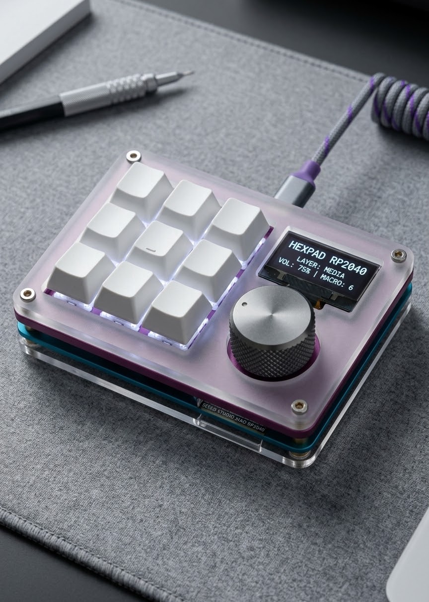
Features: Six programmable mechanical keys EC11 rotary encoder Encoder push-button input 0.91-inch I2C OLED display Seeed Studio XIAO microcontroller USB-C connection Cherry MX-compatible switch footprints Custom PCB shape B.Cu ground plane KiCad source files included
Project StatusThe PCB is currently under development.
Schematic completed - done Components assigned to footprints- done PCB routed - done Ground zone added - done Electrical Rules Check completed - done Design Rules Check completed - done Mounting holes added - done Physical footprints verified - not yet Gerber files generated - not yet PCB ordered - not yet Firmware completed - not yet Final board assembled and tested- Not yet PCB Preview
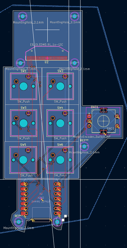
PCB Editor
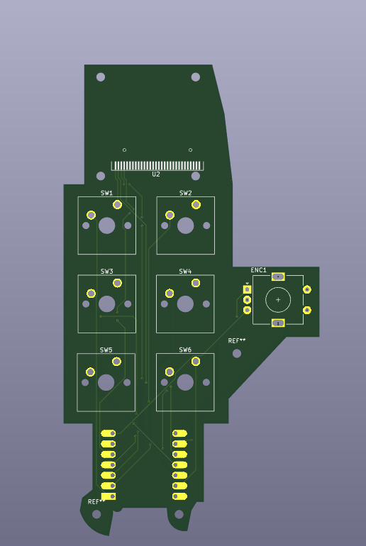
Front 3D view
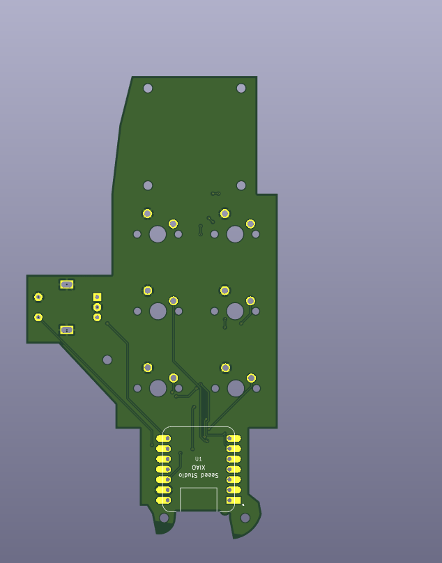
 Back 3D view
 Schematic
 The buttons are connected between individual GPIO pins and GND. The firmware will use the microcontroller's internal pull-up resistors.
The OLED uses I2C:
VCC to 3.3 V GND to GND SDA to the XIAO SDA pin SCL to the XIAO SCL pin The rotary encoder uses:
A to a GPIO pin B to a separate GPIO pin C to GND S1 to a GPIO pin S2 to GND Bill of Materials Quantity Component Description 1 Seeed Studio XIAO Exact model: Seeed Studio XIAO RP2040 Plus 6 Mechanical switches Cherry MX-compatible PCB-mount switches - Vendor 6 Keycaps Standard 1U keycaps 1 Rotary encoder EC11-compatible encoder with push button 1 Encoder knob Knob matching the encoder shaft 1 OLED display 0.91-inch I2C OLED 1 Custom PCB Two-layer PCB 2 or 4 M2 screws For mounting the PCB 2 or 4 M2 standoffs Height depends on the enclosure Hardware Files The KiCad project files are located in the hardware/ directory.
Macrpadilius.kicad_pro Macrpadilius.kicad_sch Macrpadilius.kicad_pcb Firmware The firmware will support:
Six programmable keys Rotary encoder clockwise and counterclockwise inputs Rotary encoder push button OLED status information Multiple macropad layers or modes Firmware development has not been completed yet.
Manufacturing Before manufacturing, verify:
The exact EC11 encoder dimensions OLED module dimensions and pin order XIAO footprint and USB-C orientation Cherry MX switch compatibility Keycap and encoder-knob clearance Mounting-hole locations Copper-to-edge clearance DRC results Gerber and drill-file output Do not manufacture the PCB before comparing every footprint with the exact physical component or its mechanical drawing.
Assembly Planned assembly order:
Inspect the manufactured PCB. Test continuity between power and GND. Solder the Seeed Studio XIAO or its sockets. Solder the OLED header. Solder the rotary encoder. Install and solder the six switches. Inspect every solder joint. Connect the board through USB-C. Upload test firmware. Test every switch, encoder signal, and OLED connection. Designed With KiCad Arduino IDE or PlatformIO Seeed Studio XIAO GitHub License A license has not been selected yet.
Possible options include:
MIT License for firmware CERN Open Hardware Licence Version 2 for PCB hardware Creative Commons for documentation and images Author Created by Sergel Hasabella
tl;dr, This project being made is a a 6 button macropad with screen and a knob (7th), most of the work is done and uploaded
| Qty | Value | Footprint | References |
|---|---|---|---|
| 6 | SW_Push | Button_Switch_Keyboard:SW_Cherry_MX_1.00u_PCB | SW1, SW2, SW3, SW4, SW5, SW6 |
| 1 | ER_OLEDM0.91_1x-I2C | Display:OLED-128O064D | U2 |
| 1 | MOUDLE-SEEEDUINO-XIAO | Xiao thimgy:XIAO-Generic-Hybrid-14P-2.54-21X17.8MM | U1 |
| 1 | RotaryEncoder_Switch_MP | Rotary_Encoder:RotaryEncoder_Alps_EC11E-Switch_Vertical_H20mm | ENC1 |
The 9 most common of 16 parts.
It measures 62 × 114.2 mm and has 2 copper layers, 1.6 mm thick.
16 parts. The full list of its parts is on this page, with links to each part's symbol and footprint where PCBKit's library has them.
From the Sergel1/Hacklife_-Macrospadius repository on GitHub, at the commit this page was made from: the board is hardware/Macrpadilius.kicad_pro.kicad_pcb and its schematic hardware/Macrpadilius.kicad_sch. PCBKit opens the board in the browser, with nothing to install.
Its repository states no licence, so its author keeps all rights: ask Sergel1 before reusing the design.
google/mozc-devices
Circuit diagrams and firmware source code for Gboard DIY keyboards

conorpp/u2f-zero
U2F USB token optimized for physical security, affordability, and style

rusefi/rusefi
rusefi - GPL internal combustion engine control unit

VoronDesign/Voron-Hardware
Cool Hardware designed by the Voron Design group

hoglet67/RGBtoHDMI
Bare-metal Raspberry Pi project that provides pixel-perfect sampling of Retro Computer RGB/YUV video and conversion to HDMI

hackclub/OnBoard
💡 Join 1,000 teenagers and make your first PCB with a $100 grant!

