
2 layers216.9 × 86.8 mm
Sweepv2
davidphilipbarr/Sweep
Sweep - a small promicro based keyboard inspired by the Ferris.
51 parts2.1k

Digital Vinyl system implemented using System Verilog on Basys3 development board
Dvs is an open-source printed circuit board by semitechen, from the semitechen/DVS_Basys3 repository on GitHub, published under the MIT licence. It is a 2-layer board of 38.4 × 71.4 mm with 51 parts on 50 nets, routed with 167 tracks and 105 vias.
Its parts include 36 resistors, 9 capacitors, 5 connectors and 1 IC. It belongs with the fPGA and programmable logic boards of this library.






An autonomous, ultra-low-latency Digital Vinyl System (DVS) and lossless SD audio player implemented entirely in hardware on dual Digilent Basys 3 (Xilinx Artix-7) FPGA boards and custom analog front-end / R-2R DAC PCB shields.
Click the preview below to watch the complete hardware setup in action, demonstrating real-time scratch, pitch-shifting, backward playback, cueing, track selection, and autonomous QSPI Flash boot:
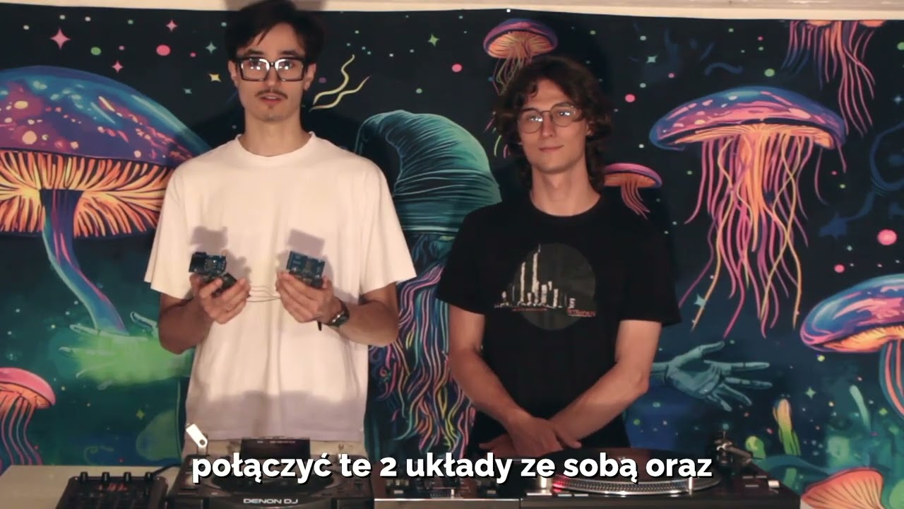
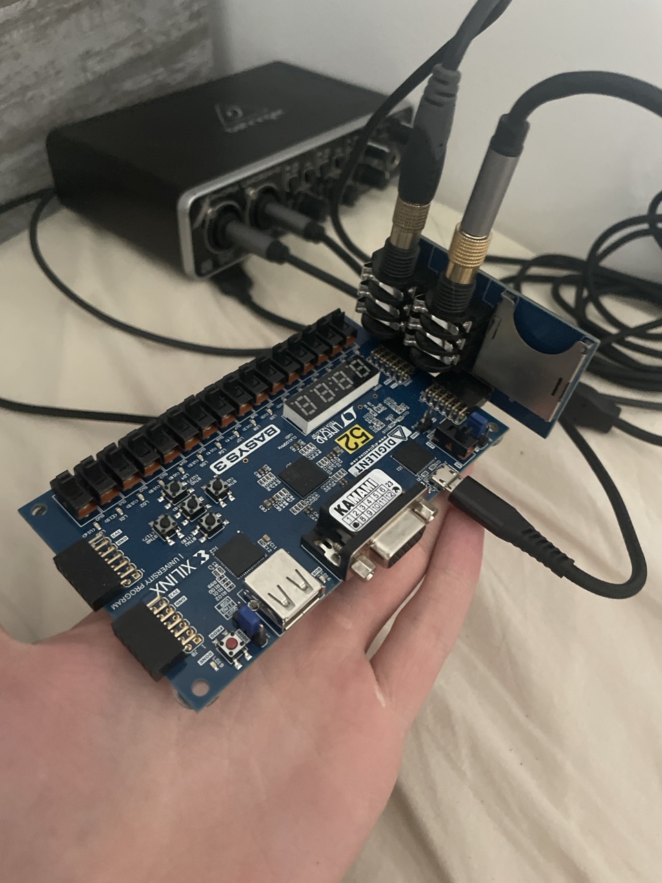
Figure 1: Complete real-time test bench with analog turntable (Serato 1 kHz timecode vinyl), custom pre-amp/filter shield, Board A (Streamer), Board B (DAC Receiver), and audio output.
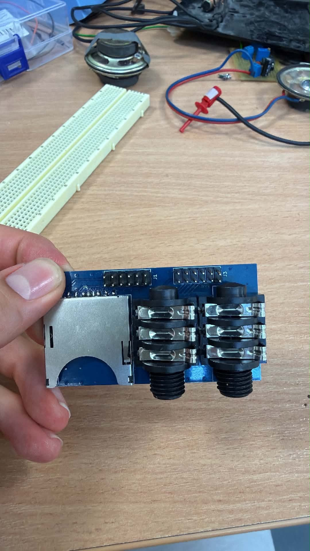
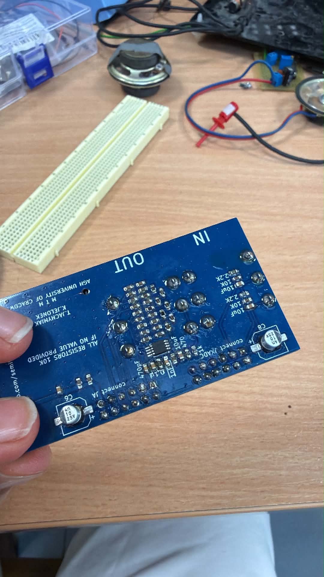
Figure 2: Custom AC-coupling pre-amplifier, active Sallen-Key low-pass filter, and 8-bit R-2R resistor ladder DAC PCB shield designed for Basys 3 Pmod headers.
In modern DJing, Digital Vinyl Systems (DVS) bridge tactile analog turntables with digital music libraries. However, commercial DVS setups require:
This project eliminates the computer entirely. By executing all timecode signal processing, quadrant phase decoding, flash memory DMA, rate modulation, and audio reconstruction directly in FPGA silicon at 100 MHz:
The project employs a distributed Dual-Board FPGA Architecture linked by a dedicated 2,000,000 baud (2 Mbps) UART audio bus:
+---------------------------------------------------------------------------------------------------------+
|                                    BOARD A: TIME-CODE STREAMER & SD PLAYER                              |
|                                                                                                         |
|  [Turntable] ---> [Custom PCB Pre-amp] ---> [XADC (vauxp6/14)]                                          |
|                                                     |                                                   |
|                                            [xadc_interface]                                             |
|                                                     | x2t (12-bit L/R @ 100 kHz)                        |
|                                                     v                                                   |
|                                          [timecode_pos_tracker] <---> [led_pos_display] (16 LEDs)        |
|                                                     |                                                   |
|                                                     | t2p (Q4.12 Speed, Direction, Squelch)             |
|                                                     v                                                   |
|  [Micro-SD] <--- [sd_card_controller] <--- [sd_bram_bridge]                                            |
|                       (16.67 MHz SPI)               | b2f (512-byte Sector Writes)                      |
|                                                     v                                                   |
|                                              [audio_fifo] (1024-byte Dual-Port BRAM)                    |
|                                                     |                                                   |
|                                                     | f2p (Read FIFO Sample)                            |
|                                                     v                                                   |
|                                         [variable_speed_player] (NCO Phase Acc)                         |
|                                                     |                                                   |
|                                                     | p2u (8-bit PCM Sample Valid)                      |
|                                                     v                                                   |
| [uart_tx] (2 Mbps Transmitter) |xadc_interface.sv)vauxp6/vauxn6 for Left, vauxp14/vauxn14 for Right).timecode_pos_tracker.sv)sd_card_controller.sv, sd_bram_bridge.sv, audio_fifo.sv)CMD17) to fetch uncompressed 512-byte PCM audio sectors into a 1024-byte dual-port Block RAM FIFO (audio_fifo.sv), maintaining an autonomous prefetch waterlevel.variable_speed_player.sv)uart_tx.sv, uart_rx.sv)K17) at 2,000,000 baud ($50\text{ clock cycles per bit}$ at 100 MHz, $0.00%\text{ baud error}$).r2r_dac.sv)The project includes a custom 2-layer PCB shield designed in KiCad 8 that mounts directly onto the Basys 3 Pmod headers (pcb/ directory):
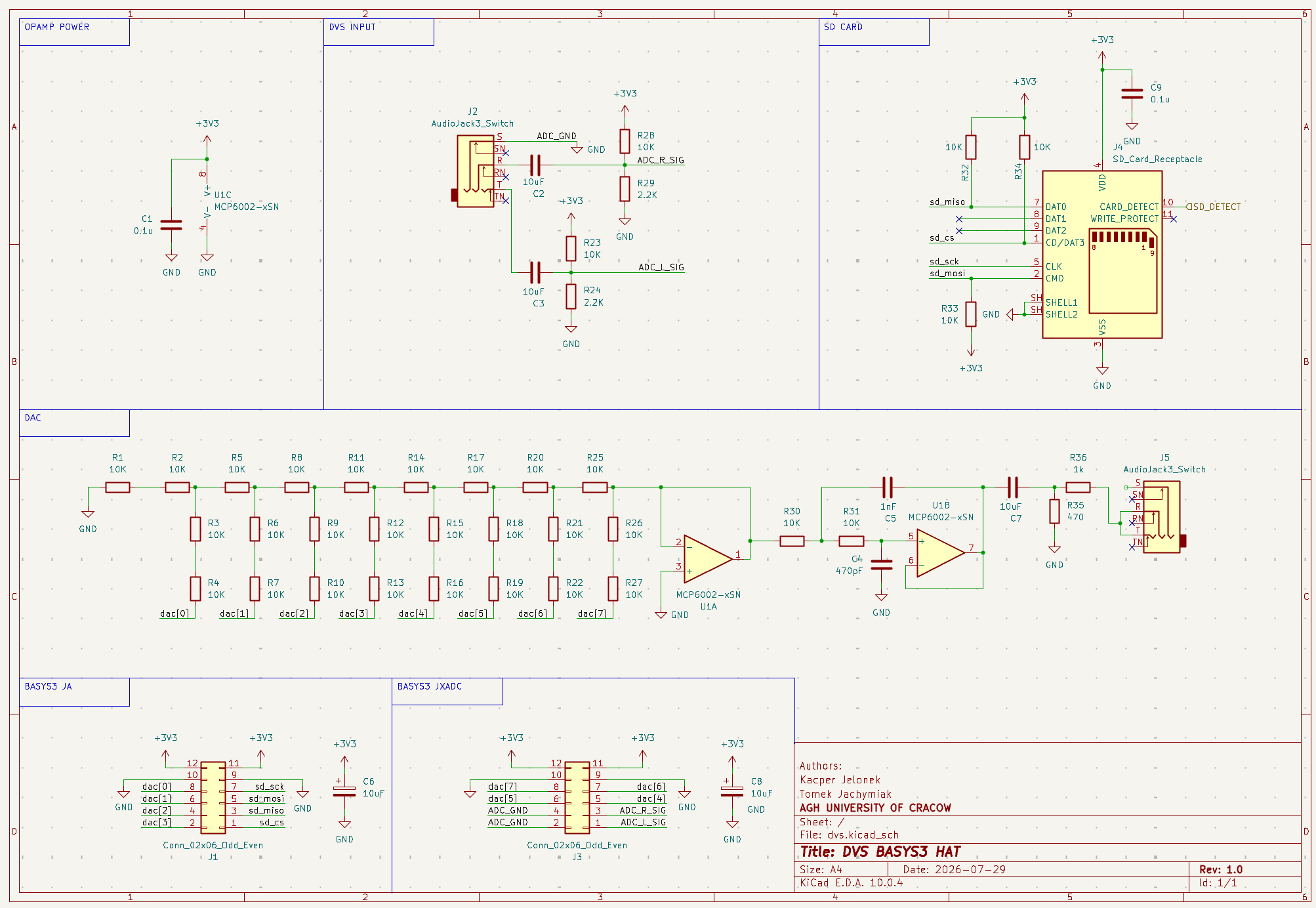
Figure 3: KiCad Schematic showing dual-channel AC coupling, DC bias network, 2nd-order active Sallen-Key low-pass filter, and 8-bit R-2R resistor DAC ladder.
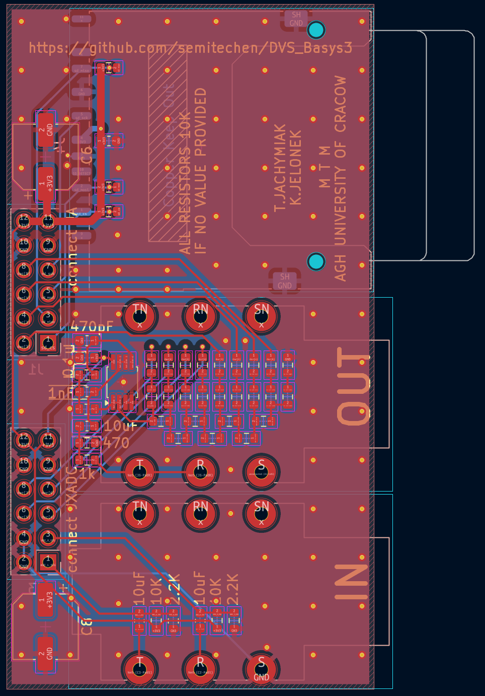
Figure 4: KiCad 2-layer PCB layout with dedicated analog/digital ground separation and ultra-compact Pmod form-factor.
top_board_a_streamer)| Function | Basys 3 Pin | Header / Pin Name | Description |
|---|---|---|---|
| System Clock | W5 | CLK | 100.00 MHz onboard oscillator |
| Global Reset | U18 | BTNC | Pushbutton active-high synchronous reset |
| Track Next | T18 | BTNU | Advance to next audio track |
| Track Prev | U17 | BTND | Return to previous audio track |
| Mode Switch | V17 | SW0 | 1 = DVS Vinyl Control, 0 = Standalone Auto-Play |
| Timecode L+ / L- | J3 / K3 | Pmod JXADC Pin 1 / 7 | Left channel differential input (vauxp6/vauxn6) |
| Timecode R+ / R- | L3 / M3 | Pmod JXADC Pin 2 / 8 | Right channel differential input (vauxp14/vauxn14) |
| SD SPI CS | J1 | Pmod JA Pin 1 | Micro-SD Card Chip Select (active-low) |
| SD SPI MISO | L2 | Pmod JA Pin 2 | Micro-SD Master-In Slave-Out (pull-up enabled) |
| SD SPI MOSI | J2 | Pmod JA Pin 3 | Micro-SD Master-Out Slave-In |
| SD SPI SCK | G2 | Pmod JA Pin 4 | Micro-SD SPI Clock (16.67 MHz) |
| UART Audio TX | K17 | Pmod JC Pin 1 | 2 Mbps serial audio transmitter to Board B |
| Ground (GND) | GND | Pmod JC Pin 5/11 | Common ground reference line |
| Platter LEDs | LED[12:0] | Onboard LEDs | One-hot rotating vinyl position indicator |
| Squelch LED | LED13 | Onboard LED | Needle presence indicator ($> 20\text{ mV}$) |
| Direction LED | LED14 | Onboard LED | 1 = Forward, 0 = Reverse scratch |
| Heartbeat LED | LED15 | Onboard LED | 100 MHz clock live blinker |
top_board_b_dac)| Function | Basys 3 Pin | Header / Pin Name | Description |
|---|---|---|---|
| System Clock | W5 | CLK | 100.00 MHz onboard oscillator |
| Global Reset | U18 | BTNC | Reset watchdog and DAC state |
| UART Audio RX | K17 | Pmod JC Pin 1 | 2 Mbps serial audio receiver from Board A |
| Ground (GND) | GND | Pmod JC Pin 5/11 | Common ground reference line |
| DAC Bit 0..3 | G3, H2, K2, H1 | Pmod JA Pins 10, 9, 8, 7 | R-2R ladder lower nibble (dac[0..3]) |
| DAC Bit 4..7 | M2, M1, N2, N1 | Pmod JXADC Pins 3, 9, 4, 10 | R-2R ladder upper nibble (dac[4..7]) |
| VU-Meter LEDs | LED[11:0] | Onboard LEDs | 12-LED dynamic audio level bargraph |
| Watchdog LED | LED14 | Onboard LED | Audio stream activity monitor |
| Heartbeat LED | LED15 | Onboard LED | 100 MHz clock live blinker |
Both boards can run autonomously without a computer attached:
JP1 (MODE) jumper header and set the jumper block to QSPI (middle pin bridged to the top pin).# Flash Board A (Timecode Streamer)
./tools/program_fpga.sh -t board_a -f -s <SERIAL_BOARD_A>
# Flash Board B (DAC Engine)
./tools/program_fpga.sh -t board_b -f -s <SERIAL_BOARD_B>Synthesized and implemented for Xilinx Artix-7 XC7A35T-1CPG236C in Vivado 2023.2:
| Resource | Available | Board A (Streamer) | Utilization A | Board B (DAC) | Utilization B |
|---|---|---|---|---|---|
| Slice LUTs | $20,800$ | 984 | 4.73% | 248 | 1.19% |
| Slice Registers (FF) | $41,600$ | 1,142 | 2.75% | 286 | 0.69% |
| Block RAM Tile | $50$ | 1.5 | 3.00% | 0.0 | 0.00% |
| DSP48E1 Slices | $90$ | 1 | 1.11% | 0 | 0.00% |
| XADC Primitives | $1$ | 1 | 100.00% | 0 | 0.00% |
| Bonded IOB Pins | $106$ | 25 | 23.58% | 26 | 24.53% |
| Global Clock BUFG | $32$ | 1 | 3.12% | 1 | 3.12% |
| Target Module | Worst Negative Slack (WNS) | Total Negative Slack (TNS) | Worst Hold Slack (WHS) | Status |
|---|---|---|---|---|
top_board_a_streamer | +0.278 ns | 0.000 ns | +0.073 ns | MET (0 Violations) |
top_board_b_dac | +0.504 ns | 0.000 ns | +0.119 ns | MET (0 Violations) |
top_dvs_basys3 (Single) | +0.312 ns | 0.000 ns | +0.084 ns | MET (0 Violations) |
Build Quality Metric: 0 Errors, 0 Critical Warnings.
DVS_Basys3/
├── doc/                            # Official course submission documents & PDF schematics
│   ├── lista_kontrolna_KJ_TJ_2026.docx
│   ├── raport_KJ_TJ_2026.docx
│   └── schemat.pdf
├── fpga/
│   ├── constraints/                # Dedicated XDC pinout constraints per board
│   │   ├── top_board_a_streamer.xdc
│   │   ├── top_board_b_dac.xdc
│   │   └── top_dvs_basys3.xdc
│   └── scripts/                    # Non-project mode Vivado build & program scripts
│       ├── generate_bitstream.tcl
│       ├── project_details.tcl
│       └── program_fpga.tcl
├── pcb/                            # KiCad 8 hardware project files
│   ├── dvs.kicad_pcb
│   ├── dvs.kicad_pro
│   └── dvs.kicad_sch
├── pictures/                       # High-resolution hardware & schematic photos
│   ├── full_hardware.jpeg
│   ├── custom_pcb_photo1.jpg
│   ├── custom_pcb_photo2.jpg
│   ├── schematic_kicad_screenshot.png
│ └── pcb_kicad_screenshot.pngExecute testbenches with Vivado xsim:
./tools/run_simulation.sh timecode_pos_tracker
./tools/run_simulation.sh sd_card_controller
./tools/run_simulation.sh audio_fifoGenerate bitstream and raw .bin files:
# Build Board A (Streamer)
./tools/remote_build.sh board_a

# Build Board B (DAC Engine)
./tools/remote_build.sh board_b

# Build Single-Board Integrated Target
./tools/remote_build.sh integratedConvert MP3/WAV tracks to raw 8-bit unsigned PCM ($44.1\text{ kHz}$ mono):
# Convert track and write to SD sector
python3 tools/wav_to_sd.py my_track.wav --track 0 --disk /dev/diskNCourse: Układy Elektroniczne Cyfrowe 2 (UEC2), AGH University of Krakow (AGH UST).
Supervisor: mgr inż. Piotr Kaczmarczyk (kaczmarczyk@agh.edu.pl).
| Qty | Value | Footprint | References |
|---|---|---|---|
| 32 | 10K | Resistor_SMD:R_0603_1608Metric | R1, R2, R10, R11, R12, R13, R14, R15, R16, R17, R18, R19, R20, R21, R22, R23 +16 |
| 3 | 10uF | Capacitor_SMD:C_0603_1608Metric | C2, C3, C7 |
| 2 | 0.1u | Capacitor_SMD:C_0603_1608Metric | C1, C9 |
| 2 | 10uF | Capacitor_SMD:CP_Elec_6.3x5.4 | C6, C8 |
| 2 | 2.2K | Resistor_SMD:R_0603_1608Metric | R24, R29 |
| 2 | AudioJack3_Switch | Connector_Audio:Jack_6.35mm_Neutrik_NMJ6HFD2-AU_Horizontal | J2, J5 |
| 2 | Conn_02x06_Odd_Even | Connector_PinSocket_2.54mm:PinSocket_2x06_P2.54mm_Vertical | J1, J3 |
| 1 | 1k | Resistor_SMD:R_0603_1608Metric | R36 |
| 1 | 1nF | Capacitor_SMD:C_0603_1608Metric | C5 |
| 1 | 470 | Resistor_SMD:R_0603_1608Metric | R35 |
| 1 | 470pF | Capacitor_SMD:C_0603_1608Metric | C4 |
| 1 | MCP6002-xSN | Package_SO:MSOP-8_3x3mm_P0.65mm | U1 |
| 1 | SD_Card_Receptacle | Connector_Card:SD_Kyocera_145638009511859+ | J4 |
It measures 38.4 × 71.4 mm and has 2 copper layers, 1.6 mm thick.
51 parts. The full list of its parts is on this page, with links to each part's symbol and footprint where PCBKit's library has them.
From the semitechen/DVS_Basys3 repository on GitHub, at the commit this page was made from: the board is pcb/dvs.kicad_pcb and its schematic pcb/dvs.kicad_sch. PCBKit opens the board in the browser, with nothing to install.
Its repository publishes it under the MIT licence: you may reuse it on that licence's terms (keep the author's notice, and for a copyleft licence share your changes alike).
davidphilipbarr/Sweep
Sweep - a small promicro based keyboard inspired by the Ferris.


W0rthlessS0ul/nRF24_jammer
The nRF24 jammer is a powerful tool that requires an ESP32 and configurable numbers of NRF24 modules to assemble.

hackclub/OnBoard
💡 Join 1,000 teenagers and make your first PCB with a $100 grant!


Neumi/open_echo
Open Source echo sounder / depth sounder / SONAR for bathymetry and research. Arduino based and compatible.


vsfteam/vsf
Versaloon Software Framework -- a tiny preemptive-capable event-driven incremental software framework for embedded systems