2 layers325.5 × 240.1 mm
 second-string/capacitive-touch-slider-board-prototype
Protoype hardware and firmware for evaluating different designs of capacitive touch sliders
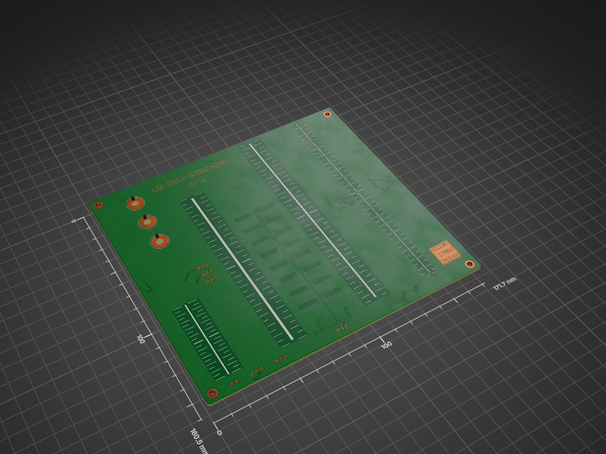
Slider rev 1 0 is an open-source printed circuit board by second-string, from the second-string/capacitive-touch-slider-board-prototype repository on GitHub, published under the MIT licence. It is a 2-layer board of 171.7 × 160.5 mm with 159 parts on 172 nets, routed with 857 tracks and 142 vias.
It is built around the AT42QT2160-MMU, AT42QT2120-XU and 74HCT595D. Its parts include 95 resistors, 16 diodes, 16 transistors, 11 connectors and 7 capacitors.


This repo contains a design for a prototype PCB for testing different capacitive touch slider designs. For more information on the different slider footprints, see writeup.
There is a schematic PDF and PCB layer prints PDF in the version 1.0 directory if you do not have KiCad. There are also Excel and interactive BOMs in the bom/ subdirectory.
Reach out if you would like the KiCad slider schematic symbol and footprint files, they are saved in my global library and so not directly accessible from the project directory.
There is test firmware in slider-board_rev_1_0/bringup_firmware/. NOTE: This firmware is sloppy, terribly written, inefficient, and everything is hardcoded. It is only included as a reference, do not think that this will work for you out of the box.
Videos of example behavior are in the img/ directory.
| Qty | Value | Footprint | References |
|---|---|---|---|
| 32 | 1k2 | Resistor_SMD:R_0603_1608Metric | R11, R12, R13, R15, R16, R18, R19, R21, R22, R23, R24, R26, R27, R28, R29, R31 +16 |
| 18 | 1k | Resistor_SMD:R_0603_1608Metric | R14, R20, R25, R30, R33, R35, R36, R60, R61, R62, R63, R64, R65, R66, R67, R68 +2 |
| 16 | 470R 1/2W | Resistor_SMD:R_0603_1608Metric | R69, R70, R71, R72, R73, R74, R75, R76, R77, R78, R79, R80, R81, R82, R83, R84 |
| 16 | LED | LED_SMD:LED_SunLED_XZ_Reverse_Mount | D1, D2, D3, D4, D5, D6, D7, D8, D9, D10, D11, D12, D13, D14, D15, D16 |
| 16 | Q_NMOS_GSD | Package_TO_SOT_SMD:TSOT-23 | Q1, Q2, Q3, Q4, Q5, Q6, Q7, Q8, Q9, Q10, Q11, Q12, Q13, Q14, Q15, Q16 |
| 8 | 10k | Resistor_SMD:R_0603_1608Metric | R4, R5, R6, R37, R38, R95, R96, R97 |
| 8 | 2k4 | Resistor_SMD:R_0603_1608Metric | R8, R10, R32, R34, R39, R40, R58, R59 |
| 6 | 2k | Resistor_SMD:R_0603_1608Metric | R85, R86, R87, R92, R93, R94 |
| 5 | 0.1uF | Capacitor_SMD:C_0603_1608Metric | C1, C2, C4, C6, C7 |
| 4 | 1k5 | Resistor_SMD:R_0603_1608Metric | R88, R89, R90, R91 |
| 4 | MountingHole_Pad | MountingHole:MountingHole_3.2mm_M3_DIN965_Pad | H1, H2, H3, H4 |
| 3 | 47k | Resistor_SMD:R_0603_1608Metric | R1, R17, R48 |
| 3 | Conn_01x03_Pin | Connector_PinHeader_2.54mm:PinHeader_1x03_P2.54mm_Vertical | J2, J4, J5 |
| 3 | Jumper_3_Bridged12 | Connector_PinHeader_2.54mm:PinHeader_1x03_P2.54mm_Vertical | JP1, JP2, JP3 |
| 3 | ~ | Button_Switch_SMD:Cap_Touch_Ring_Small | P2, P5, P6 |
| 2 | 4.7nF | Capacitor_SMD:C_0603_1608Metric | C3, C5 |
| 2 | 74HCT595 | Package_DFN_QFN:DHVQFN-16-1EP_2.5x3.5mm_P0.5mm_EP1x2mm | U4, U5 |
| 2 | AT42QT2160-MMU | Package_DFN_QFN:VQFN-28-1EP_4x4mm_P0.45mm_EP2.4x2.4mm_ThermalVias | U2, U3 |
| 2 | TestPoint | TestPoint:TestPoint_Pad_D3.0mm | TP1, TP2 |
| 1 | AT42QT2120 | Package_SO:TSSOP-20_4.4x6.5mm_P0.65mm | U1 |
| 1 | Conn_01x02_Pin | Connector_PinHeader_2.54mm:PinHeader_1x02_P2.54mm_Vertical | J3 |
| 1 | Slider_Resistive_3P_1L | Touch:Slider_ResistiveInterpolation_3P_1L | P7 |
| 1 | Slider_Spatial_3P_1L | Touch:Slider_SpatialInterpolation_3P_1L | P1 |
| 1 | ~ | Touch:Slider_ResistiveInterpolation_7P_2L | P8 |
| 1 | ~ | Touch:Slider_ResistiveInterpolation_Thin_7P_2L | P9 |
It measures 171.7 × 160.5 mm and has 2 copper layers, 1.6 mm thick.
159 parts, built around the AT42QT2160-MMU, AT42QT2120-XU and 74HCT595D. The full list of its parts is on this page, with links to each part's symbol and footprint where PCBKit's library has them.
From the second-string/capacitive-touch-slider-board-prototype repository on GitHub, at the commit this page was made from: the board is slider-board_rev_1_0/slider_rev_1_0.kicad_pcb and its schematic slider-board_rev_1_0/3-pad-sliders.kicad_sch. PCBKit opens the board in the browser, with nothing to install.
Its repository publishes it under the MIT licence: you may reuse it on that licence's terms (keep the author's notice, and for a copyleft licence share your changes alike).


DuPAL-PAL-DUmper/DuPAL_Board
This repository contains the KiCad files and the gerber files for the DuPAL boards.


listofoptions/TH-XWhatsIt
through hole implementation of the capsense controllers by XWhatsIt

Fluepke/Fluepdot
Project for controlling Annax flipdot panels used by the Berliner Verkehrsbetriebe

vascofazza/cloxie_nixie_clock
Schematics and code for Cloxie: my Nixie Tube Clock.