
2 layers86 × 70 mm
AVR488
VE7PMC/AVR488
USB to IEEE-488 interface based on the ATmega168/328 microcontroller
28 parts10GPL-3.0

 scrouthtv/vfd-clock
Building a clock from VFD tubes
Nixie is an open-source printed circuit board by scrouthtv, from the scrouthtv/vfd-clock repository on GitHub, published under the GPL-3.0 licence. It is a 2-layer board with 32 parts on 55 nets, routed with 433 tracks and 0 vias.
It is built around the ATMEGA168-20PU. Its parts include 13 resistors, 13 transistors, 5 connectors and 1 IC. It belongs with the lEDs and displays boards and the AVR (ATmega, ATtiny) boards of this library.
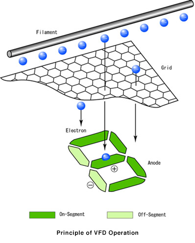
The manufacturer has a good explanation of the concept of VFD tubes on their website.
They basically work like this:
In the simplest case, the anodes make up an 8-figure consisting of seven individual segments plus a decimal point as an eigth segment. More complicated designs such as combining multiple letters of different size, adding in symbols or colors.
Each anode has its own wire leaving the casing. The whole tube must be "activated" by setting the grid to a higher potential compared to the filament, which allows for multiplexing multiple tubes.
Image Source: VFD | Futaba Corporation
I recently got ten VFD tubes labelled as Futaba DG10Q1 3GS out of an old calculator that was due for trash:
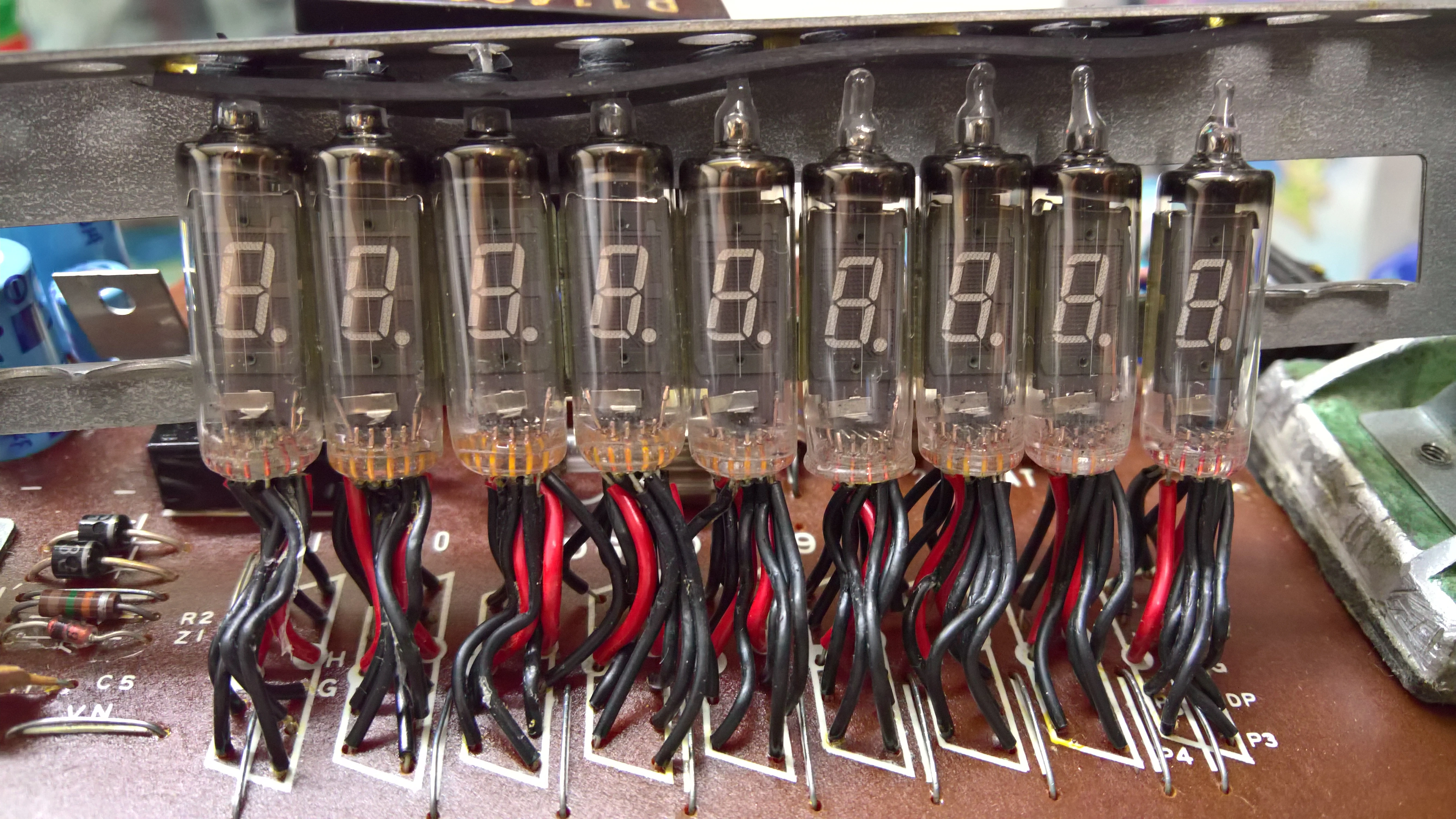
The manufacturer has been "selling gas-discharge display tube [since] 1968". Sadly, they want to leave the business until the end of this year (2021).
The tubes themselves look fantastic:
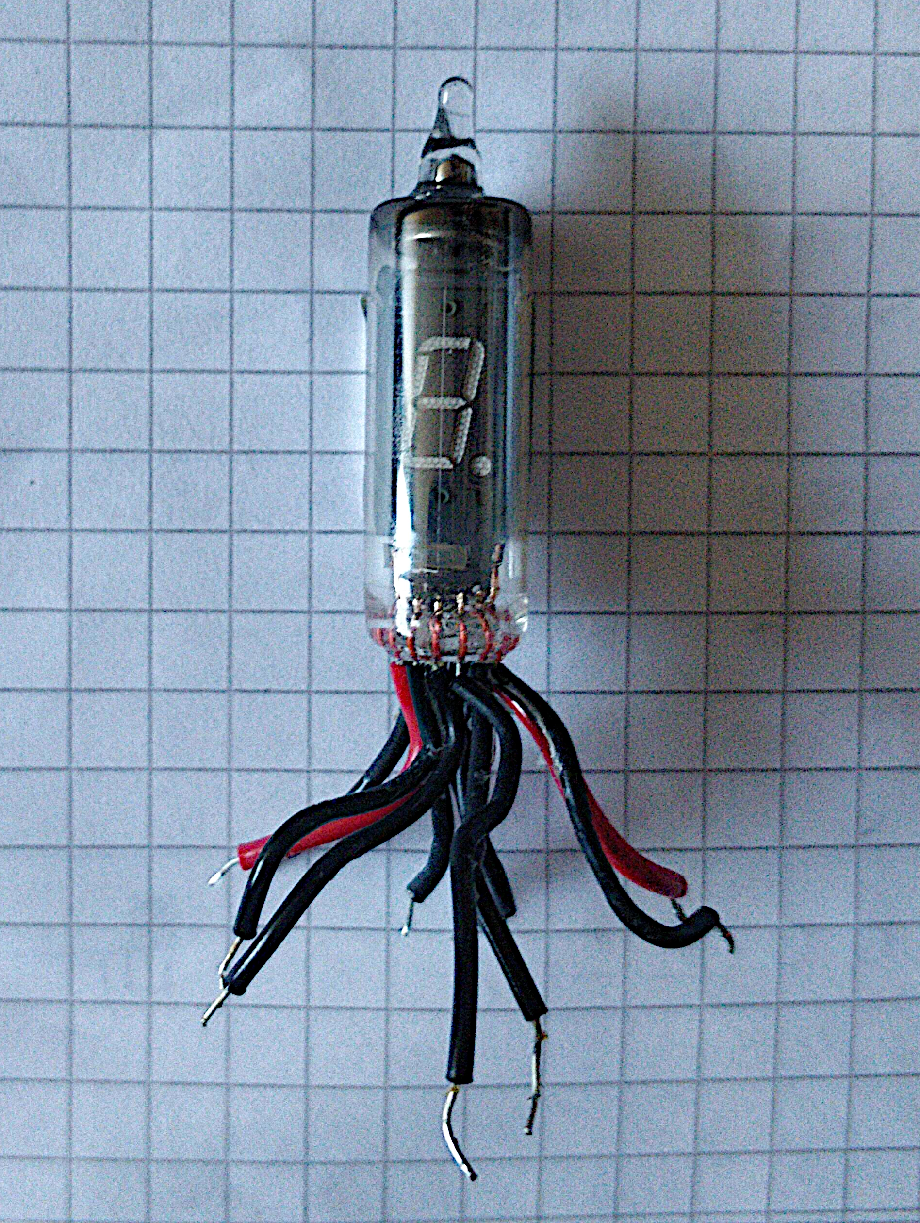
Image Source: Used with permission, own work.
I wasn't able to find a datasheet online, only this image that circulates on the internet:
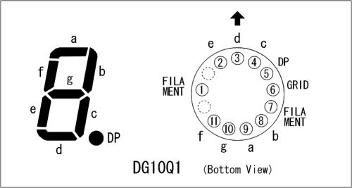
Keep in mind that this is the bottom view.
The filament in this tube is a thin wire in the front center that runs from the bottom to the top. It glows orange-ish after applying a high enough current to it.
My tubes have a set of red-colored wires for the filament. If yours don't, try to find the pair of pins wich has the lowest resistance (lower than 10 ohms).
Slowly increasing the voltage across these two pins, they started glowing at around 0.8 V.
As a next step, I applied 18 V to both the grid and a segment to see it glowing.
Image Source: DG10Q1 | AsahiNet
I am planning on combining multiple tubes to get a "smart" clock which is controlled by an atmega328 chip (the chip that is also used in an Arduino). The atmega can then be combined with a Raspberry Pi which controls the displayed text.
In the end, I'll need at least a 5 V power supply for the logic.
The filament basically carries all the load of the tube. I found that a single DG10Q1 consumes up to 50 mA at 1 V!
The easiest way would be to use a voltage regulator which creates 1 V from my 5 V supply. However, many common voltage regulators use a reference voltage of 1.25 V (e.g. LM317 or MAX1733) and can't be adjusted to anything below 1.25 V (without an overly complicated circuit).
Because of this issue, I am using a type of current mirror circuit instead:
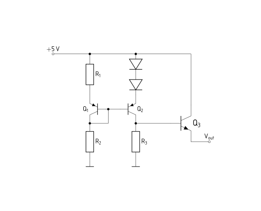
Technically, it is used to mirror the amps from an input to the output.
However, with the correct value for R3, an arbitrary output voltage can be set.
TODO: this is not correct and needs more work
Image source: Own work.
| Qty | Value | Footprint | References |
|---|---|---|---|
| 13 | 2N7000 | Package_TO_SOT_THT:TO-92_Inline | Q1, Q2, Q3, Q4, Q5, Q6, Q7, Q8, Q9, Q10, Q11, Q12, Q13 |
| 8 | R | Resistor_THT:R_Axial_DIN0207_L6.3mm_D2.5mm_P10.16mm_Horizontal | R6, R7, R8, R9, R10, R11, R12, R13 |
| 5 | 10k | Resistor_THT:R_Axial_DIN0207_L6.3mm_D2.5mm_P10.16mm_Horizontal | R1, R2, R3, R4, R5 |
| 5 | DG10Q1_DIL | DG10Q1:DG10Q1_DIL_2.54mm | J1, J2, J3, J4, J5 |
| 1 | ATmega168-20PU | Package_DIP:DIP-28_W7.62mm | U1 |
32 parts, built around the ATMEGA168-20PU. The full list of its parts is on this page, with links to each part's symbol and footprint where PCBKit's library has them.
From the scrouthtv/vfd-clock repository on GitHub, at the commit this page was made from: the board is cad/nixie.kicad_pcb. PCBKit opens the board in the browser, with nothing to install.
Its repository publishes it under the GPL-3.0 licence: you may reuse it on that licence's terms (keep the author's notice, and for a copyleft licence share your changes alike).
VE7PMC/AVR488
USB to IEEE-488 interface based on the ATmega168/328 microcontroller

Rbara00/Rob-Bara-College-Coding-Portfolio
Robert Bara's Electrical Engineering College portfolio


hoglet67/RGBtoHDMI
Bare-metal Raspberry Pi project that provides pixel-perfect sampling of Retro Computer RGB/YUV video and conversion to HDMI

hackclub/OnBoard
💡 Join 1,000 teenagers and make your first PCB with a $100 grant!


octosavvi/ESPKey
Wiegand data logger, replay device and micro door-controller