6 layers138.2 × 101.3 mm

 screwbreaker/ScartPCB33
A little PCB to buld a SCART cable for console and old computers
ScartPCB is an open-source printed circuit board by screwbreaker, from the screwbreaker/ScartPCB repository on GitHub. It is a 4-layer board of 39.5 × 21 mm with 55 parts on 36 nets, routed with 152 tracks and 42 vias.
It is built around the TPS61040DBVRG, BC847W and BC857W. Its parts include 12 resistors, 5 capacitors, 2 diodes, 2 transistors and 1 IC. It belongs with the retro computing and games boards of this library.


A little PCB to buld a SCART cable for console and old computers

This is a little PCB made to make easy to assemble a SCART cable for console and old computers.
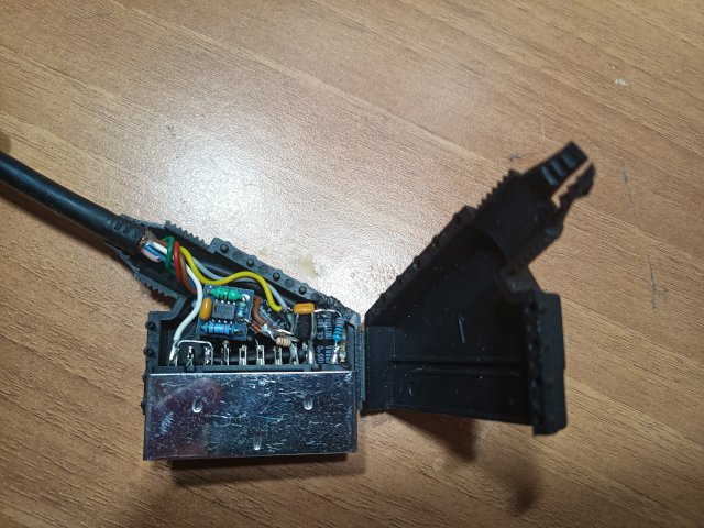
As anyone else I always made my SCART cables by hand, using THT components. And by soldering them directly on the SCART connector. And that's pefectly fine. Except for systems like the Mega Drive, that require a lot of componets to be fitted in a small space. So I thought to build a little PCB that fit inside the SCART connector in oder to make everything more easy and clean.
As example here a comparison between my old handmade cable, and the new one with this PCB:

Of course, there are other project like this around. But none of them have all the stuff I wanted. My requirements was a buffer for the csync and a boost converter for the 12V.
My original plan was to make a PCB for each console. But, I managed this PCB in a way that can be used almost in any case. With this PCB is possible to make a SCART cable for almost every console and computer. It is pretty versatile. And is made to fit inside the cheapest SCART connectors available online.
The components value in the schematic and in the BOM are for a PAL Mega Drive. For other systems, refer to the SCART diagram of the secific system.
The PCB allow to put components in series and in parallel with the signals. This allow to use this PCB to buld almost any SCART cable for almost any system.
To make a Mega Drive cable is necessary to put a 220uF capacitor in series with the RGB signals, since is really complicated to find small, and cheap SMD capacitors of this value, the PCB allow to put multiple capacitors in parallel. So, to make a 220uF capacitor is possible to put two 100uF 1206 plus one 22uF 0603. Probably the 22uF are not really required, but I found the space for some extra footprint in the PCB, so the total value can be easily adjusted.
For example to make a SNES cable put a 0 ohm resistor in place of RR1, RG1, RB1, and place a 75 ohm resitor to ground on each singal by using RR2, RG2, RB2.
If you have a mono audio, like in the first model of Mega Drive, is possible to close the MONO jumper, this short toghether the left and right channel.
The video buffer is there mostly for the Mega Drive, it is nor required on most of the other systems. To bypass the video buffer, close the NOBUF jumper, in this case do not populate any components on the buffer section.
The RGB jumper can be left open on systems that don't have an RGB output, like a C64.
In general, choose the components to match what do you need to make your video cable. By using 0 ohm resistors as jumper is possible to make almost any combination.
The Mega Drive have a problem with the csync signal. The csync is connected to the input pin of the encoder, not to the output pin. This can cause some issue on some TV sets. That's why I placed a buffer on the line.
The csync on the Mega Drive is also a TTL level signal, to compensate this a 300-470 ohm reistor can be placed in series with the signal to reduce the voltage to something more like to the standard. Most of the time also a 220uF capacitor in series with the signal is required. Not only the Mega Drive use a TTL signal on the csync, it cab be present also on other systems.
Unfortunately not all TV do like this values for the csync line. So, the values can be adjusted to match your TV set requirements. Be careful with the level of the signals, they must be in a range that do not cause any damage to your TV.
The values on the csync line, that are on the schematic or in the BOM are for a PAL Mega Drive. With this set of components I can use my modded MD on my TV, by switching from PAL to NTSC withouth any issue.
Other systems don't have this issue. The buffer can be bypassed if not needed by closing the NOBUF jumper. In this case, do not populate any component on the buffer section.
There is a little boost converter to step up the 5V and get the 12V required for the 4:3 aspect ration. This is the only way to have the switch voltage. Some systems, like Amiga or SNES do have the 12V on the connector. But, due to the small space on the PCB, is not possible to use it.
The BOM is for a PAL Mega Drive. To make SCART cables for other system choose the components according to the specific schematic. Use 0 ohm resistors as jumper where needed.
For the boost converter TPS61040DBVR and TPS61041DBVR are equivalent for this application.
For the buffer any pair of complementary transistors can be used, the package must be SC-70 or equivalent.
Unfortunately, due to the space constraints inside the SCART connector, this PCB is a 4 layer board. And for the same reason, some components are 0402.
The PCB still very cheap to produce, since it is very small, and it use standard vias and traces.
Soldering 0402 components by hand require a bit of skill on soldering.
All the SCART connectors I bought have an hawful issue. The cable gland, the plastic thing that close the SCART shell, is made out the most brittle material in the world.
Initially, I thought that this was because I bought the cheapest SCART connector available on internet.
However even the ones bought on trusth resellers or on electronic shops have this issue.
So, I made a replacement that can be 3D printed. It's far to be perfect, I have no skills on 3D printing. But it do the job.

The PCBs are under the CERN OHL license. The firmwares, under the GPL3.
This is an OPEN project. So, like any other project like this, the hope is that others can improve it an reshare with the community. Don't go out this basic guideline.
The hardware and the software are provided to you 'as is' and without any express or implied warranties whatsoever with respect to its functionality, operability or use, including, without limitation, any implied warranties of merchantability, fitness for a particular purpose or infringement. We expressly disclaim any liability whatsoever for any direct, indirect, consequential, incidental or special damages, including, without limitation, lost revenues, lost profits, losses resulting from business interruption or loss of data, regardless of the form of action or legal theory under which the liability may be asserted, even if advised of the possibility or likelihood of such damages.
| Qty | Value | Footprint | References |
|---|---|---|---|
| 12 | Conn_01x01 | Footprints:PAD2x2 | JI1, JI2, JI3, JI4, JI5, JI6, JI7, JI8, JI9, JI10, JI11, JI12 |
| 8 | 100uF | Capacitor_SMD:C_1206_3216Metric | CB1, CB2, CC1, CC2, CG1, CG2, CR1, CR2 |
| 5 | DNC | Resistor_SMD:R_0402_1005Metric | R8, RB2, RC2, RG2, RR2 |
| 4 | 22uF | Capacitor_SMD:C_0603_1608Metric | CB3, CC3, CG3, CR3 |
| 3 | 75 | Resistor_SMD:R_0402_1005Metric | RB1, RG1, RR1 |
| 3 | Jumper_2_Open | Jumper:SolderJumper-2_P1.3mm_Open_TrianglePad1.0x1.5mm | JP1, JP2, JP3 |
| 2 | 100nF | Capacitor_SMD:C_0402_1005Metric | C0, C4 |
| 2 | 1M | Resistor_SMD:R_0402_1005Metric | R5, R6 |
| 2 | D_Schottky | Diode_SMD:D_0402_1005Metric | D1, D2 |
| 1 | 0 | Resistor_SMD:R_0402_1005Metric | R7 |
| 1 | 1.6M | Resistor_SMD:R_0402_1005Metric | R1 |
| 1 | 10pF | Capacitor_SMD:C_0402_1005Metric | C2 |
| 1 | 10uH | Inductor_SMD:L_0603_1608Metric | L1 |
| 1 | 180 | Resistor_SMD:R_0402_1005Metric | R9 |
| 1 | 1K | Resistor_SMD:R_0402_1005Metric | R3 |
| 1 | 1uF | Capacitor_SMD:C_0402_1005Metric | C3 |
| 1 | 200K | Resistor_SMD:R_0402_1005Metric | R2 |
| 1 | 300 | Resistor_SMD:R_0402_1005Metric | RC1 |
| 1 | 4.7uF | Capacitor_SMD:C_0402_1005Metric | C1 |
| 1 | BC847W | Package_TO_SOT_SMD:SOT-323_SC-70 | Q1 |
| 1 | BC857W | Package_TO_SOT_SMD:SOT-323_SC-70 | Q2 |
| 1 | Conn_02x10_Odd_Even | Footprints:SCART | J1 |
| 1 | TPS61040DBVR | Footprints:TPS61040DBVR | U1 |
It measures 39.5 × 21 mm and has 4 copper layers, 1.58 mm thick.
55 parts, built around the TPS61040DBVRG, BC847W and BC857W. The full list of its parts is on this page, with links to each part's symbol and footprint where PCBKit's library has them.
From the screwbreaker/ScartPCB repository on GitHub, at the commit this page was made from: the board is ScartPCB.kicad_pcb and its schematic ScartPCB.kicad_sch. PCBKit opens the board in the browser, with nothing to install.
Its repository states no licence, so its author keeps all rights: ask screwbreaker before reusing the design.


ixoo/rpi-dsi-iphone4
A rpi compute module (or CMIO) MIPI DSI adapter for the iPhone 4 lcd.


Harshavar8jdm/tps61040dbvr-boost-converter-module
A compact (18 mm × 14 mm) 2-layer DC-DC step-up converter module designed around the Texas Instruments TPS61040 boost switching regulator.


tyevco/dial-me-spinner
A Bluetooth dial spinner about 70 mm across, built on the nRF52840. A heavy, balanced stainless flywheel ring spins around a stationary centre that holds a colour OLED and a ring of 48 addressable RGB LEDs.

punkfab/pcb-corpus
235 real KiCad boards from open-source hardware repositories, prepared as a placement and routing benchmark