
4 layers330.2 × 304.8 mm
 scrapcomputing/MCEBlaster96
A Pi Pico based MDA/CGA/EGA to VGA adapter
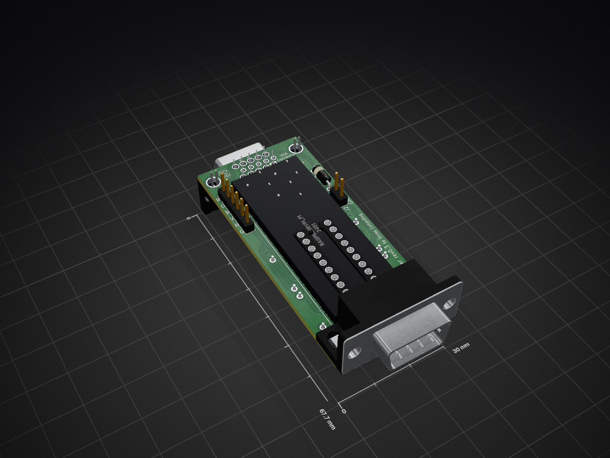
MCEBlaster is an open-source printed circuit board by scrapcomputing, from the scrapcomputing/MCEBlaster repository on GitHub, published under the GPL-2.0 licence. It is a 2-layer board of 30 × 67.7 mm with 19 parts on 45 nets, routed with 398 tracks and 17 vias.
It is built around the 74FCT245APC. Its parts include 6 resistors, 4 connectors, 2 ICs, 1 capacitor and 1 diode. It belongs with the interfaces and adapters boards and the RP2040 boards of this library.
A versatile standalone MCA/CGA/EGA TTL to VGA adapter based on a raspberry pi Pico.
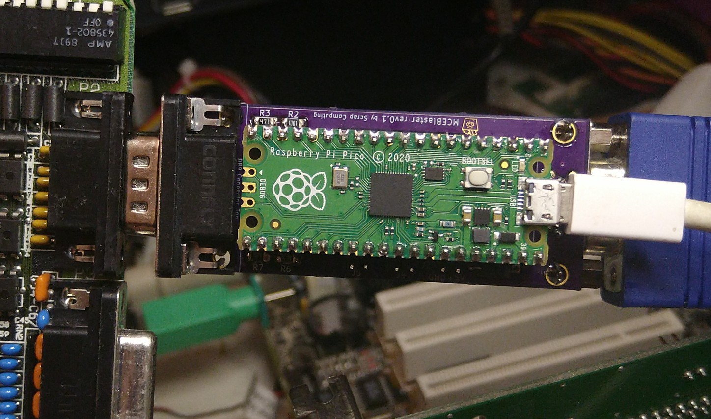
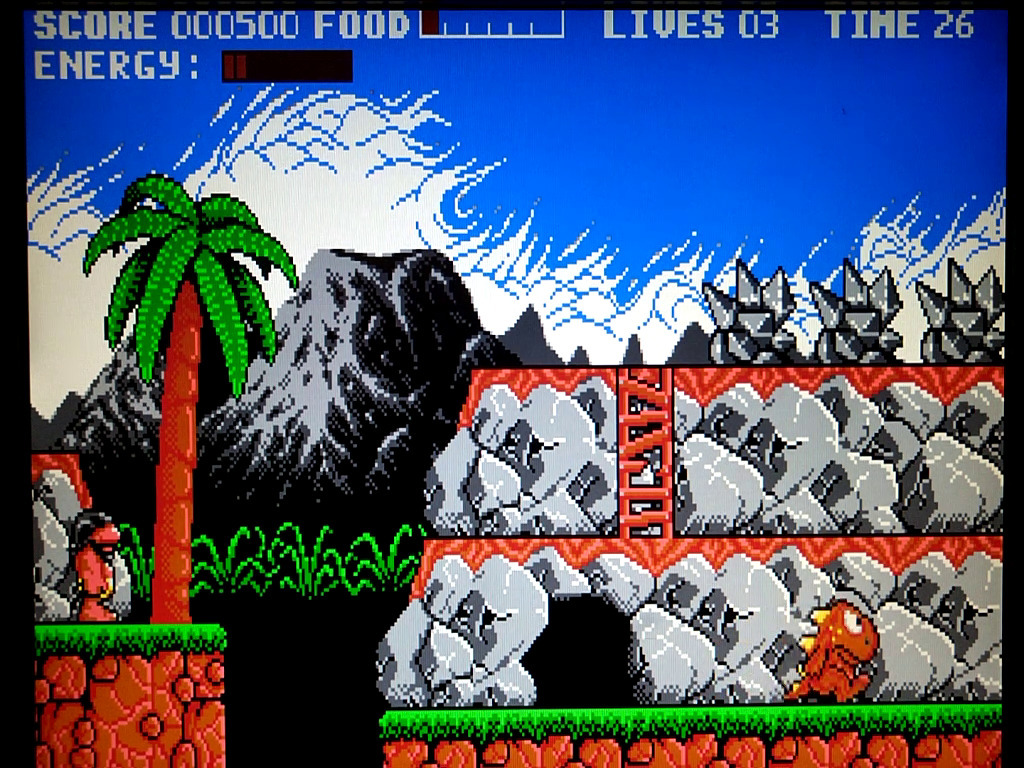
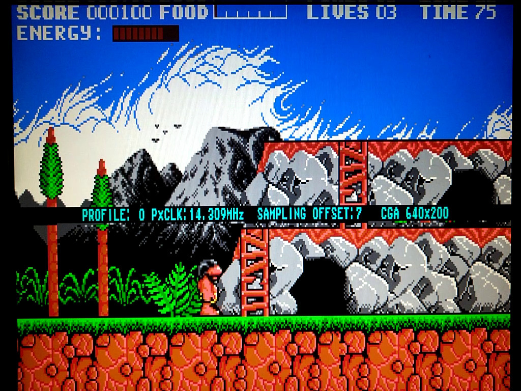
The Pico reads the TTL input video signal, writes the pixels to a buffer and then generates the VGA signal using the pixels from the buffer.
MCEBlaster_pico1.uf2 or MCEBlaster_pico2.uf2 firmware to the drive associated with the PicoNOTE: Controls have changed since version 0.2!
PIXEL CLOCK button once, this will enter the pixel adjust mode. This should show text on screen displaying the current pixel clock.PIXEL CLOCK to increment the pixel clock by 10KHz.AUTO ADJUST to decrement the pixel clock by 10KHz.PIXEL CLOCK to increment the pixel clock by 1 KHz.AUTO ADJUST to decrement the pixel clock by 1 KHz.PIXEL CLOCK to increment the sampling offset and then increment the pixel clock by 1 KHz once we have tried all offsets.AUTO ADJUST to decrement the sampling offset and then decrement the pixel clock by 1 KHz once we have tried all offsets.The sampling offset is a fine-tuning knob added in rev 0.3 that shifts TTL sampling to try to avoid sampling the pixels during the transitions (shown as X).
In this example, using a sampling offset of 1 will result in a very noisy image because sampling takes place during the pixel transitions.
                    _____ _____ _____ _____
TTL Pixels:        X_____X_____X_____X_____X
Sampling offset 0:      |     |     |     |
Sampling offset 1:       |     |     |     |
Sampling offset 2:        |     |     |     |
Sampling offset 3:         |     |     |     |
The reason why offsets are needed and a demonstration of how they work can be found in video part 3.
AUTO ADJUST button. This works best when the image shown is full from border to border.Long-pressing the PIXEL CLOCK button will show a screen with information about the TTL signal.
Note: this is not updated in real-time.
You can exit the screen by pushing any button.
By default the MCE Blaster will automatically detect the TTL mode by checking the VSync frequency and the VSync Polarity. If these match the standard MDA/CGA/EGA modes used in PCs this will usually work fine.
But since Version 0.2 the MCE Blaster also supports manually setting:
The operation is straight forward:
[<selected>]. For example: Currently
Selected Horiz Offset Vertical Offset
vvv vvv vvv
MANUAL-TTL [CGA] 640 x 200 X: AUTO Y: AUTO
^ ^ ^ ^
On/Off TTL-mode Horiz x Vertical Resolutionthe currently selected option is CGA.
Occasionally the user may save to flash some configuration that makes the MCE Blaster unusable or inoperable. In this case you can reset to defaults by pressing both buttons while powering on the device. Upon a successful reset you will see the LED blinking fast for about 2 seconds. You can release the buttons after that and the MCE Blaster will start with the default settings.
The MCE Blaster supports a number of profiles, which helps when swapping video cards. The settings for one card can be at Profile 0, the settings for another card can be at Profile 1 etc. The default profile is Profile 0.
Changing profiles is as easy as long-pressing the AUTO ADJUST button and cycling through the profiles with either the AUTO ADJUST or the PIXEL CLOCK button.
Profiles are demonstrated briefly in video part 3.
The first core reads the TTL video data (through the level-shifter) from a PIO state-machine and places the pixels onto a buffer in memory. The second core works completely independently from the first core and reads the pixel from the buffer and feeds them, along with the necessary Horizontal and Vertical Sync signals to a PIO state machine that writes to GPIO outputs. The output is converted to analogue with the help of a simple R-2R DAC consisting of two resistors. Feel free to check out the video part 1 for a visual overview.
The PIO state machines are used not only receiving the TTL video data and writing the VGA video data, but also for other helper functions including:
The TTL video input is read by a PIO state-machine (one version for each video mode). But getting it to sample the pixels at the right time requires us adjust the sampling period in a precise way to match the TTL video card's internal pixel clock. Using the PIO clock divider does not give us a good-enough precision, because the fractional part of the divider is an 8-bit number, meaning that we get precision of ~0.004ns, but what we really need is about 0.001ns. So what we do is that we have multiple implementations of the state-machine code, each with a different sampling period and we look for the one that has the lowest division error using the PIO's 8-bit divider. This process is explained in more detail in the video part 2.
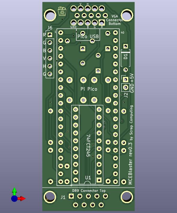
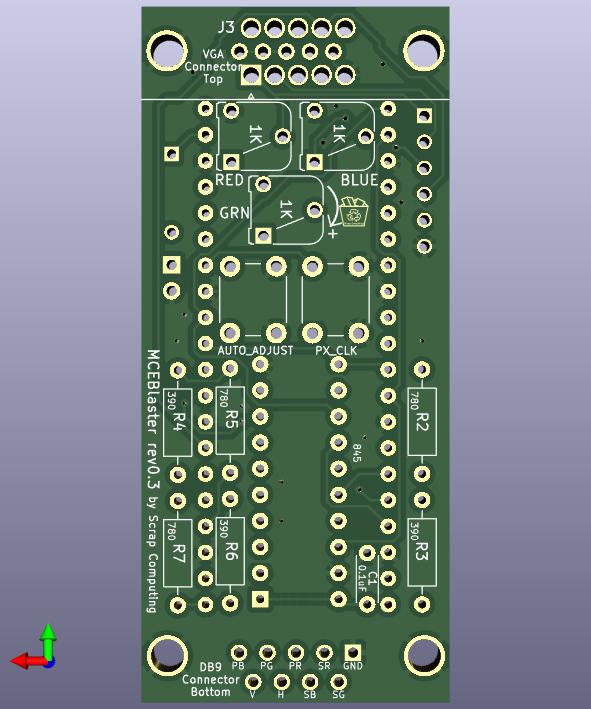
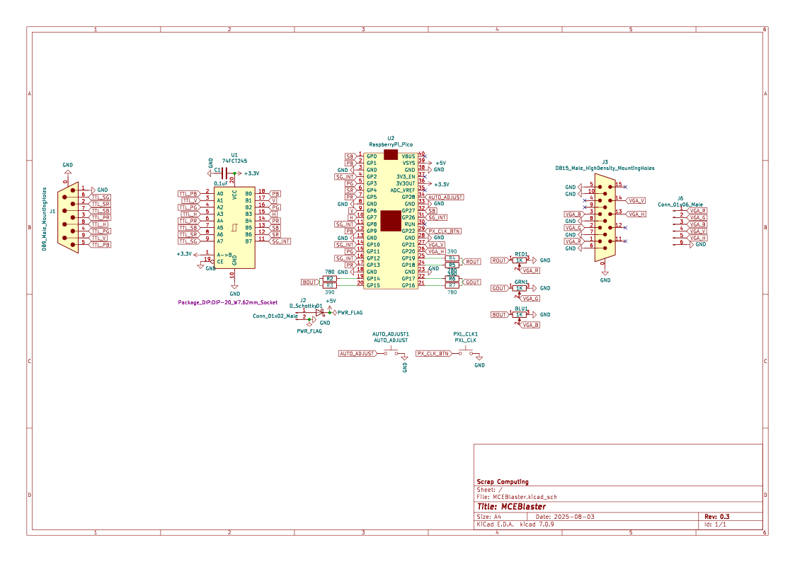
Download gerbers: https://github.com/scrapcomputing/MCEBlaster/releases
NOTE: You can still use the latest firmware with old revisions of the PCB, they are fully compatible.
| Reference | Quantity | Value | Description |
|---|---|---|---|
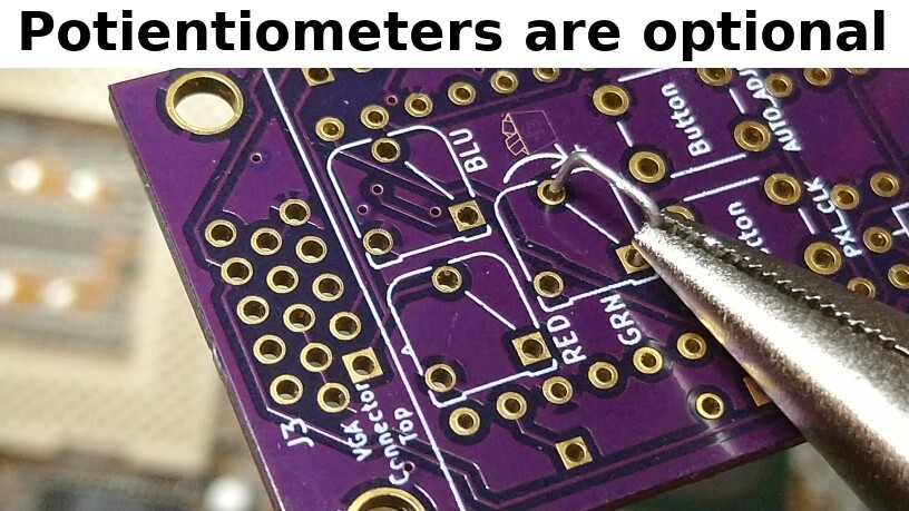
| N/A | 3 | 1K Rm065 through-hole linear potentiometer (optional: can be replaced by a wire between 2 pins as shown on PCB and the photo below | Adjust R G B VGA signals |
| C1 | 1 | 0.1uF disk ceramic capacitor | Decoupling capacitor for level-shifter IC |
| D1 | 1 (optional) | Diode Through-hole (e.g., Schottky 1N5817 or silicon 1N4001) | For powering the MCE Blaster from the PC (instead of the Pico's micro-USB) |
| J2 | 1 (optional) | 1x02 through-hole Male PinHeader 2.54mm | For alternative external power |
| J1 | 1 | DB9 Male Horizontal | For connecting to TTL video card |
| J3 | 1 | DB15 Female HighDensity Connector (e.g., Kycon K61X-E15S-NJ-VESA, thanks @wrljet) | For connecting to VGA monitor |
| R3 R4 R6 | 3 | 390 Ohm Through-hole resistor 1% (alternatively 470 Ohm) | For VGA signal DAC |
| R2 R5 R7 | 3 | 780 Ohm Through-hole resistor 1% (alternatively 1K Ohm) | For VGA signal DAC |
| SW1,SW2 | 2 | 6mm Through-hole push button | Auto-adjust and pixel-clock buttons |
| U1 | 1 | 74LVC245A DIP-20 (e.g., SN74LVC245AN) (+ optional socket) | Level-shifter IC (NOTE: in the video I am using an 74HCT245 which turns out operates out of spec) |
| U2 | 1 | RaspberryPi Pico (or Pico 2) | Pi Pico (or Pico 2) |
| N/A (for Pico) | 2 | 1x20 female through-hole pin-header 2.54mm pitch | PCB Pico headers |
| N/A (for Pico) | 2 | 1x20 male through-hole pin-header 2.54mm pitch | Headers for the Pico |
They can be replaced by a wire as shown in the photo:
$ cd firmware && mkdir build && cd build
$ cmake -DPICO_BOARD=<pico|pico2> -DCMAKE_BUILD_TYPE=Release -DPICO_FREQ=270000 -DPICO_SDK_PATH=<path-to-pico-sdk> ../src/
$ make -jThe project is GPLv2.
| Qty | Value | Footprint | References |
|---|---|---|---|
| 3 | 1K | Potentiometer_THT:Potentiometer_Runtron_RM-065_Vertical | BLU1, GRN1, RED1 |
| 3 | 390 | Resistor_THT:R_Axial_DIN0207_L6.3mm_D2.5mm_P10.16mm_Horizontal | R3, R4, R6 |
| 3 | 780 | Resistor_THT:R_Axial_DIN0207_L6.3mm_D2.5mm_P10.16mm_Horizontal | R2, R5, R7 |
| 1 | 0.1uF | Capacitor_THT:C_Disc_D4.3mm_W1.9mm_P5.00mm | C1 |
| 1 | 74FCT245 | Package_DIP:DIP-20_W7.62mm_Socket | U1 |
| 1 | AUTO_ADJUST | Button_Switch_THT:SW_PUSH_6mm | AUTO_ADJUST1 |
| 1 | Conn_01x02_Male | Connector_PinHeader_2.54mm:PinHeader_1x02_P2.54mm_Vertical | J2 |
| 1 | Conn_01x06_Male | Connector_PinHeader_2.54mm:PinHeader_1x06_P2.54mm_Vertical | J6 |
| 1 | DB15_Male_HighDensity_MountingHoles | MCEBlaster:VGA_connector_both_short_and_long | J3 |
| 1 | DB9_Male_MountingHoles | Connector_Dsub:DSUB-9_Male_Horizontal_P2.77x2.84mm_EdgePinOffset4.94mm_Housed_MountingHolesOffset7.48mm | J1 |
| 1 | D_Schottky | Diode_THT:D_A-405_P7.62mm_Horizontal | D1 |
| 1 | PXL_CLK | Button_Switch_THT:SW_PUSH_6mm | PXL_CLK1 |
| 1 | RaspberryPi_Pico | MCEBlaster:raspberry_pi_pico | U2 |
It measures 30 × 67.7 mm and has 2 copper layers, 1.6 mm thick.
19 parts, built around the 74FCT245APC. The full list of its parts is on this page, with links to each part's symbol and footprint where PCBKit's library has them.
From the scrapcomputing/MCEBlaster repository on GitHub, at the commit this page was made from: the board is kicad/MCEBlaster.kicad_pcb and its schematic kicad/MCEBlaster.kicad_sch. PCBKit opens the board in the browser, with nothing to install.
Its repository publishes it under the GPL-2.0 licence: you may reuse it on that licence's terms (keep the author's notice, and for a copyleft licence share your changes alike).


hackclub/OnBoard
💡 Join 1,000 teenagers and make your first PCB with a $100 grant!

polpo/picogus
Emulation of ISA sound cards and CD-ROM on Raspberry Pi Pico (GUS, SB/Adlib, MPU-401, Tandy, CMS, Panasonic CD-ROM) with USB mouse/joystick support


nkitanov/iaq_board
IAQ Board is a DIY (Do-It-Yourself) device for measuring internal air quality


Ardumower/ardumower
Develop an open source robotic lawn mower (HW+SW reference platform)