4 layers95.6 × 73.6 mm

 scrambletools/klaw
34-key reversible split keyboard — one PCB for both halves; hotswap MX, per-key RGB, OLED, encoder, wired or wireless. KLOR-derived.
Klaw 2 is an open-source printed circuit board by scrambletools, from the scrambletools/klaw repository on GitHub, published under the GPL-3.0 licence. It is a 2-layer board of 128.6 × 98.5 mm with 71 parts on 72 nets, routed with 1,435 tracks and 280 vias.
It is built around the 1N4148W, SK6812MINI-EA and EC11N1525404, with the PJ-320A-4P among its other parts. Its parts include 18 diodes, 18 switches, 2 connectors and 1 IC. It belongs with the keyboards and input and lEDs and displays boards and the AVR (ATmega, ATtiny) boards of this library.


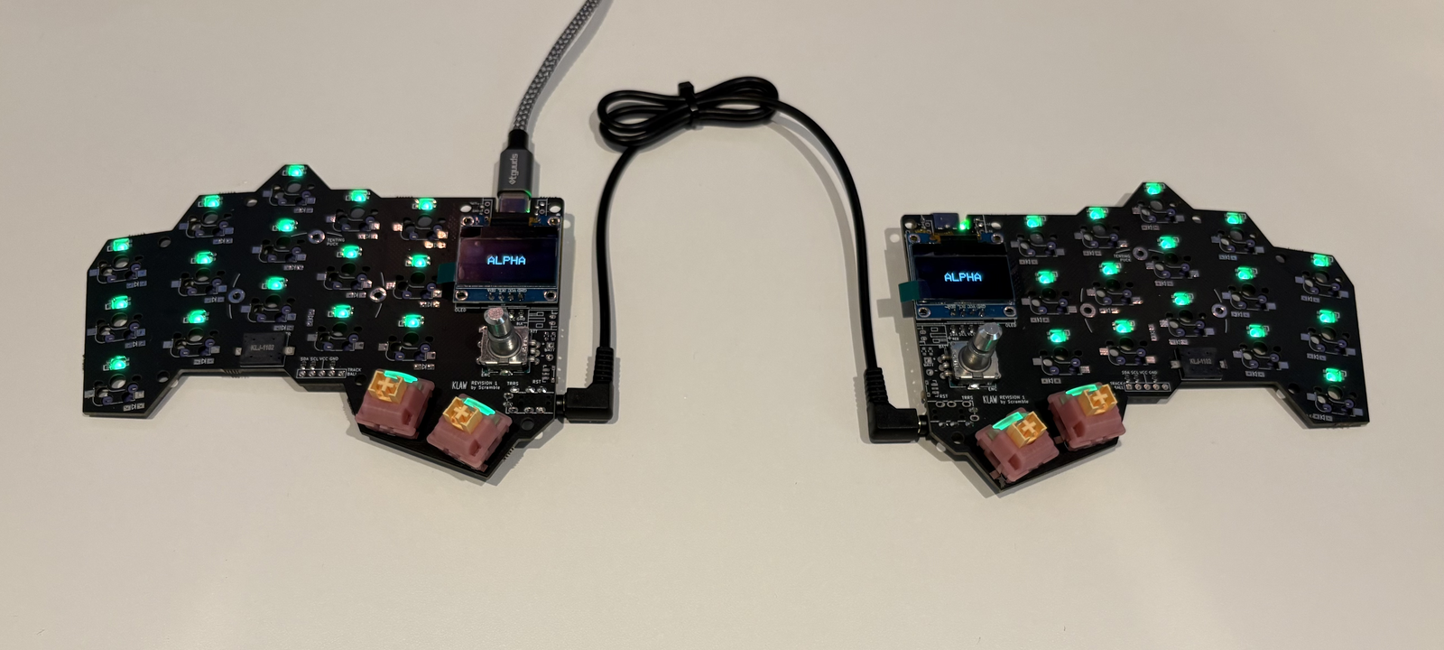
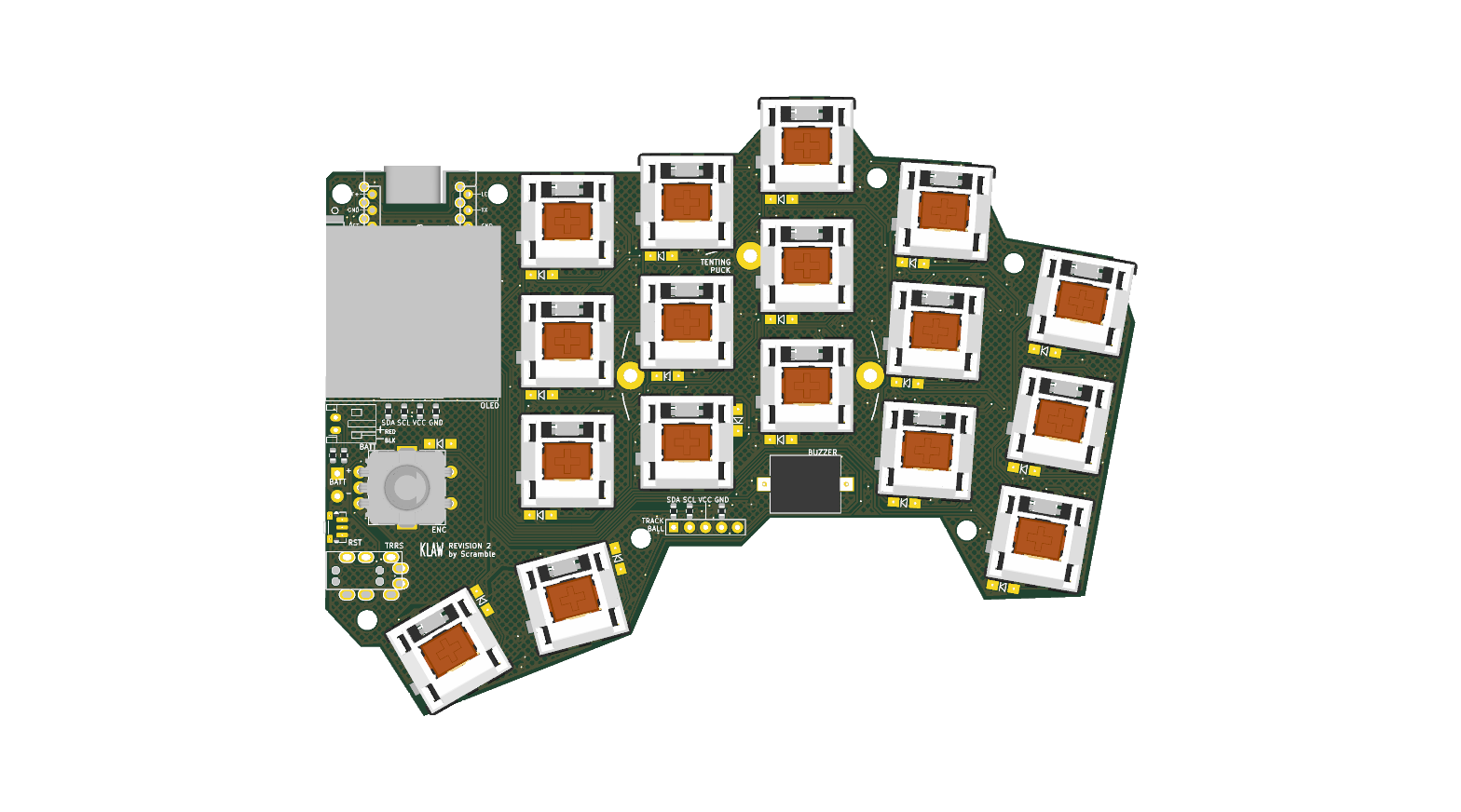
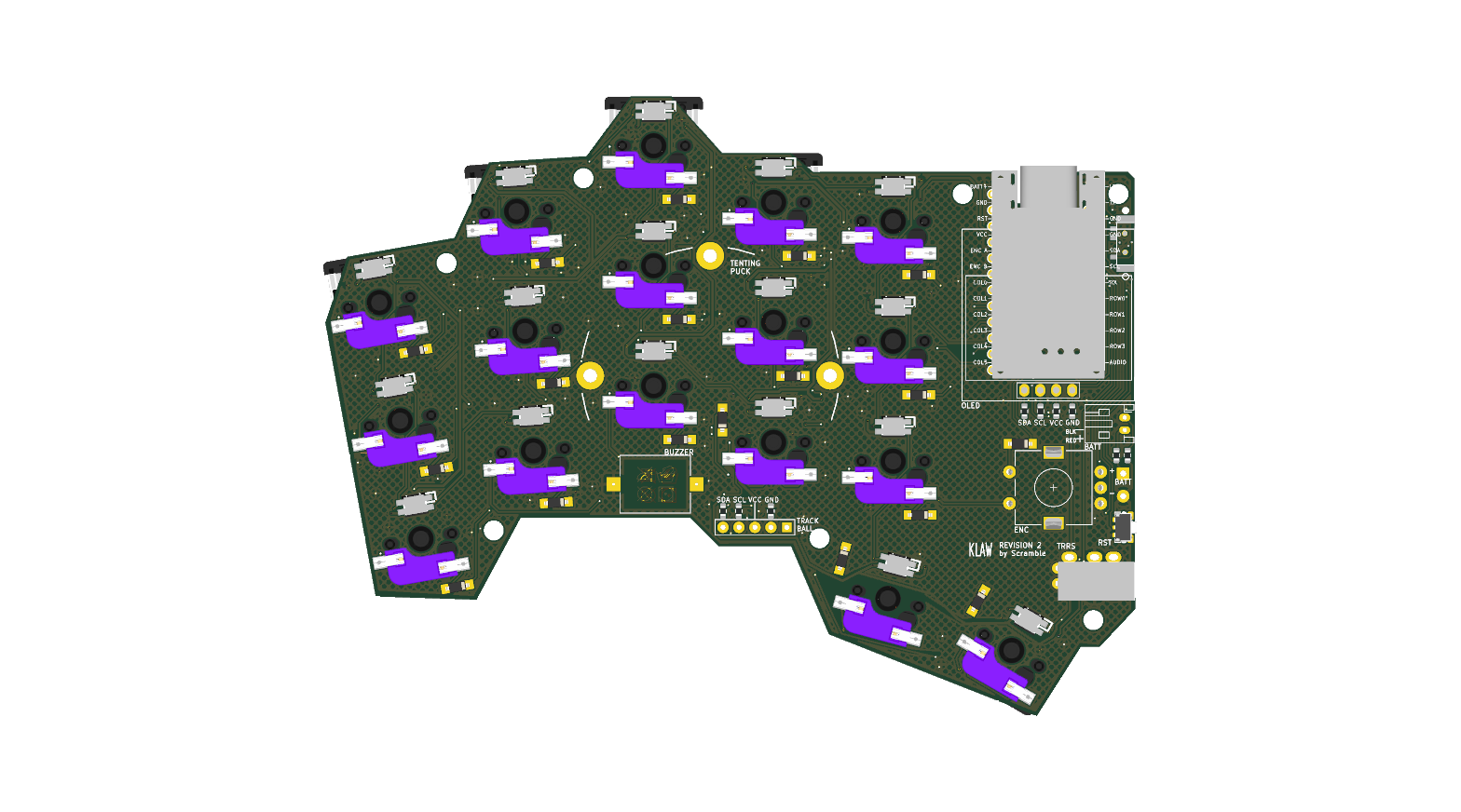
KLAW is a compact 34-key split keyboard with LEDs, OLED, buzzer and encoder. It is designed as one reversible PCB that serves both halves - components on the back face make the right half, components on the front face make the left half. One board design: the same gerber files can be used for both halves, with separate BOM and CPL files per half. Every component can be machine-assembled, but you may want to hand-assemble the MCU and OLED modules. The latest hardware revision is rev 2.
Below are renders of the right half:
| Path | Contents |
|---|---|
pcb/klaw_2/ | KiCad 10 project - schematic, board, project library with LCSC sourcing fields and 3D models |
fab/ | JLCPCB production files - gerbers, drills, BOM, placement (see fab/README.md) |
bom/ | Per-half build BOMs (bom_left.csv, bom_right.csv) with LCSC part numbers |
| - | Firmware (QMK/Vial) lives in scrambletools/klaw-firmware |
The case is designed in Plasticity and maintained outside this repository.
1. Order the PCBs. Both halves use the same board - upload
fab/klaw_2-gerbers.zip to JLCPCB (2-layer, 1.6 mm). For
machine assembly place two orders with the same gerbers: the right half
assembles on the Bottom side (fab/right-half/), the left half on the
Top side (fab/left-half/). Each order is double-sided and covers everything
solderable - see fab/README.md for the exact flow and placement-review checklist.
2. No soldering required - the assembly orders cover everything solderable:
diodes, factory-reversed per-key RGB LEDs (SK6812MINI-EA), hot-swap sockets,
TRRS, buzzer, reset switch, encoder, and each side's 0R configuration resistors
(double-sided assembly: the buzzer and encoder mount on the keycap face, every
other machine-placed part on the component face).
Mount-face tables, part numbers, prices, and per-half quantities are in bom/.
3. Add your own MX-style switches (hot-swap, no soldering), a
nice!nano-compatible controller (socket it - the MCU mounts on the bottom,
components facing the PCB, as marked on the silkscreen), a 4-pin I²C SSD1306
OLED module, and keycaps. For a wireless build, additionally fit the power
switch (C431540), JST battery connector (C173752), and a 301230-or-similar
LiPo - those three positions are DNP in the wired-first default, but their
polarity-selection resistors are already placed correctly per side.
4. Firmware. Flash the KLAW firmware (QMK/Vial) from scrambletools/klaw-firmware.
The KiCad project embeds datasheet links, LCSC part numbers, and last-checked
stock/pricing on every schematic symbol, so kicad-cli sch export bom always
gives you a current shopping list.
KLAW is a derivative of the KLOR
keyboard by GEIGEIGEIST - the layout, reversible-footprint approach, and much
of the PCB heritage come from that project. Licensed under GPL-3.0, same
as KLOR; see LICENSE.md. The Cherry MX switch 3D model comes from the
kiswitch keyswitch-kicad-library
(MIT / CC-BY-SA 4.0); the nRF52840 SuperMini controller model comes from
shnaps/garden36 (MIT).
| Qty | Value | Footprint | References |
|---|---|---|---|
| 18 | 0R | klaw:R_0603_1608Metric | JP1, JP2, JP3, JP4, JP5, JP6, JP16, JP17, JP18, JP19, JP20, JP21, JP22, JP23, JP24, JP25 +2 |
| 18 | 1N4148W | klaw:Diode_SOD123 | D1, D2, D3, D4, D5, D6, D7, D10, D12, D13, D14, D15, D16, D18, D20, D21 +2 |
| 17 | SW_PUSH-MX_W_LED | klaw:SK6812MINI_and_cherry | SW1, SW2, SW3, SW4, SW5, SW6, SW7, SW8, SW10, SW12, SW13, SW14, SW15, SW16, SW20, SW21 +1 |
| 7 | MountingHole_3.2mm_M3 | klaw:MountingHole_3.2mm_M3 | MH1, MH2, MH3, MH5, MH6, MH7, MH8 |
| 1 | Battery_Cell | klaw:custombatteryconnector_small | BT2 |
| 1 | Buzzer | klaw:Buzzer_Mallory_AST1109MLTRQ_reversible | BZ1 |
| 1 | EC11N1525404 | klaw:RotaryEncoder_Alps_EC11E-Switch_Vertical_H20mm-keebio_modified | SW18 |
| 1 | JST Connector | klaw:JST_PH_reversible | BT1 |
| 1 | PJ-320A-4P | klaw:MJ-4PP-9 | J1 |
| 1 | ProMicro | klaw:ProMicro | U1 |
| 1 | SSD1306 | klaw:SSD1306_128x64OLED | OLED1 |
| 1 | SW_DPDT_x2 | klaw:MSK12C02_reversible | PSW1 |
| 1 | SW_Push | klaw:SW_Push_1P1T-MP_NO_Horizontal_Alps_SKRTLAE010_both_sides | RSW1 |
| 1 | lv27 | klaw:lvc27_onlyInput | J3 |
The 70 most common of 71 parts.
It measures 128.6 × 98.5 mm and has 2 copper layers, 1.6 mm thick.
71 parts, built around the 1N4148W, SK6812MINI-EA, EC11N1525404 and PJ-320A-4P. The full list of its parts is on this page, with links to each part's symbol and footprint where PCBKit's library has them.
From the scrambletools/klaw repository on GitHub, at the commit this page was made from: the board is pcb/klaw_2/klaw_2.kicad_pcb and its schematic pcb/klaw_2/klaw_2.kicad_sch. PCBKit opens the board in the browser, with nothing to install.
Its repository publishes it under the GPL-3.0 licence: you may reuse it on that licence's terms (keep the author's notice, and for a copyleft licence share your changes alike).

joshajohnson/louise
A project between Josh and RiotPunch to build a 75% alice keyboard with a southpaw numpad.


mmccoyd/hillside
Family of split ergonomic keyboards with three rows of six or five keys and a generous thumb arc


