2 layers69.7 × 77.1 mm
Experimental Kit
sckim/KiCAD
휘트스톤 브리지(Wheatstone Bridge)는 저항 4개로 두 개의 분압기를 만들고, 두 중간점의 전압 차이로 저항의 균형 여부를 판단하는 회로이다. 이 예제에서는 예제 1의 흐름(회로도 → PCB)에 더해 KiCad에 내장된 SPICE 시뮬레이터(ngspice) 로 회로를 먼저 계산해 보는 방법을 익힌다.
27 partsGPL-3.0

 sckim/KiCAD
휘트스톤 브리지(Wheatstone Bridge)는 저항 4개로 두 개의 분압기를 만들고, 두 중간점의 전압 차이로 저항의 균형 여부를 판단하는 회로이다. 이 예제에서는 예제 1의 흐름(회로도 → PCB)에 더해 KiCad에 내장된 SPICE 시뮬레이터(ngspice) 로 회로를 먼저 계산해 보는 방법을 익힌다.
Adafruit nRF52 Bluefruit Feather rev G is an open-source printed circuit board by sckim, from the sckim/KiCAD repository on GitHub, published under the GPL-3.0 licence. It is a 2-layer board of 50.8 × 22.9 mm with 54 parts on 52 nets, routed with 679 tracks and 75 vias.
It is built around the CP2104EK, MDBT42Q and MCP73831T-2ACI/OT-HXY, with the DMG3415U-7 and MBR120 among its other parts. Its parts include 13 capacitors, 10 resistors, 4 ICs, 4 diodes and 4 crystals. It belongs with the microcontroller boards boards and the nRF52 and nRF5x boards of this library.


휘트스톤 브리지(Wheatstone Bridge)는 저항 4개로 두 개의 분압기를 만들고, 두 중간점의 전압 차이로 저항의 균형 여부를 판단하는 회로이다. 이 예제에서는 예제 1의 흐름(회로도 → PCB)에 더해 KiCad에 내장된 SPICE 시뮬레이터(ngspice) 로 회로를 먼저 계산해 보는 방법을 익힌다.
 |  |
이 예제는 예제 1을 마쳤다고 가정한다. 회로도 그리기, 풋프린트 지정, PCB 배선 방법은 예제 1을 참고한다.
| 파일 | 설명 |
|---|---|
WheatstoneBridge.kicad_pro | 프로젝트 파일이다. 이 파일을 연다. |
WheatstoneBridge.kicad_sch | 회로도 (시뮬레이션 설정 포함) |
WheatstoneBridge.wbk | 시뮬레이터 작업 파일(workbook)이다. 해석 종류와 명령이 저장되어 있다. |
WheatstoneBridge.kicad_pcb | PCB 레이아웃 |
gerber/ | PCB 제작 파일(거버, 드릴) |
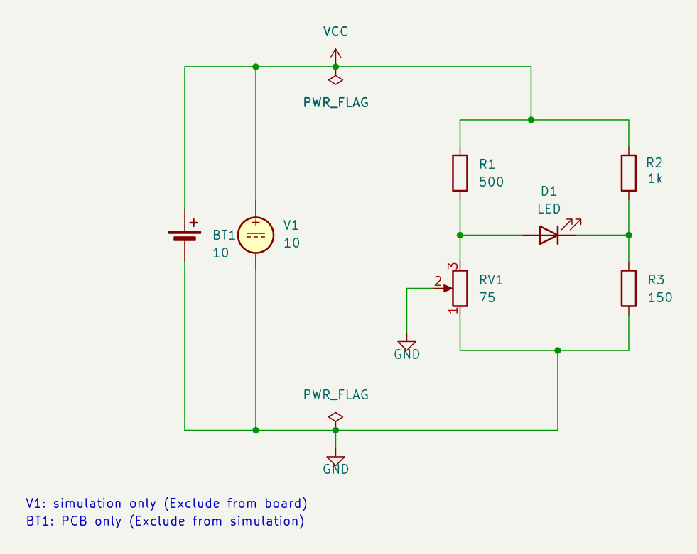
전원(10 V)과 GND 사이에 분압기 두 개가 나란히 연결되어 있다.
         VCC (10 V)
        ┌────┴────┐
        R1 500Ω   R2 1kΩ
        │         │
  A ────┤         ├──── B
        │   D1    │
        │ A ▶|─ K │          A: LED 애노드 쪽, B: LED 캐소드 쪽
        │         │
       RV1 75Ω   R3 150Ω
        └────┬────┘
GND| 참조 번호 | 부품 | 값 | 역할 |
|---|---|---|---|
| V1 | DC 전압원 (Simulation_SPICE:VDC) | 10 V | 시뮬레이션 전용 전원 (Exclude from board) |
| BT1 | 전지 (Device:Battery_Cell) | — | PCB 전용 전원 (Exclude from simulation) |
| R1, RV1 | 저항, 가변저항(트리머) | 500 Ω, 75 Ω | 왼쪽 분압기 → 점 A |
| R2, R3 | 저항 | 1 kΩ, 150 Ω | 오른쪽 분압기 → 점 B |
| D1 | LED (Device:LED) + 다이오드 모델 | — | A와 B 사이 전압 차 검출. 시뮬레이션과 PCB에 모두 쓰인다 |
두 분압기의 비율이 같으면 A와 B의 전압이 같아지고 LED에는 전류가 흐르지 않는다. 이를 평형(balanced) 상태라고 한다.
R1 / RV1 = R2 / R3 → RV1 = R1 × R3 / R2 = 500 × 150 / 1000 = 75 Ω손으로 계산한 각 점의 전압은 다음과 같다.
V_B = 10 V × R3 / (R2 + R3)   = 10 × 150 / 1150 ≈ 1.30 V   (고정)
V_A = 10 V × RV1 / (R1 + RV1)                                (RV1에 따라 변함)
RV1 pos | A–GND 사이 저항 | V_A | V_A − V_B | 상태 |
|---|---|---|---|---|
| 0 | 75 Ω | 1.30 V | 0 V | 평형 |
| 0.5 | 37.5 Ω | 0.70 V | −0.61 V | 불평형 (LED 역방향) |
| 1 | 0 Ω | 0 V | −1.30 V | 불평형 (LED 역방향) |
pos는 가변저항 와이퍼의 위치(0~1)이다. 이 회로에서는 pos = 0일 때 A–GND 사이가 75 Ω(전체)이 된다.
시뮬레이션을 돌리기 전에 이렇게 먼저 손으로 예상값을 계산해 두고, 시뮬레이션 결과와 비교하는 습관을 들인다.
시뮬레이션하려면 모든 부품에 SPICE 모델이 있어야 한다. 이 예제에서 눈여겨볼 점은 다음과 같다.
GND (접지 기호) — SPICE의 기준점(0 V)이 된다. 시뮬레이션 회로에는 접지가 반드시 하나 이상 있어야 한다. 시뮬레이션만 하는 회로라면 Simulation_SPICE:0 기호를 써도 된다.Simulation_SPICE:VDC — DC 전압원이다. Value에 전압(10)을 적는다.Device:R — 일반 저항은 따로 설정하지 않아도 KiCad가 자동으로 SPICE 저항으로 바꾼다.Device:R_Potentiometer (RV1) — 가변저항 모델(POT)을 쓰며, 전체 저항 r=75와 와이퍼 위치 pos(0~1)를 파라미터로 가진다.Device:LED (D1) — PCB에 쓰는 실제 LED 심볼에 기본 다이오드 모델(Sim.Device = D, Sim.Pins = 1=K 2=A)을 붙였다. 실제 LED의 특성과는 다르므로 "전류가 흐르는가"를 보는 정도로만 쓴다.부품의 모델은 부품을 더블클릭(E) → Simulation Model… 버튼에서 확인하고 바꿀 수 있다.
WheatstoneBridge.wbk)이 자동으로 열린다. 해석 종류는 DC 동작점 해석(.op, Operating Point) 이다.
V(...))과 소자 전류(I(...))를 확인한다.
Net-(D1-A), 점 B는 Net-(D1-K) 넷이다. 넷 이름이 길다면 회로도에서 두 점에 넷 레이블(L)로 A, B 같은 이름을 붙이면 결과를 읽기 쉬워진다.pos 값을 0, 0.5, 1로 바꿔 가며 다시 시뮬레이션한다.| 항목 | 값 |
|---|---|
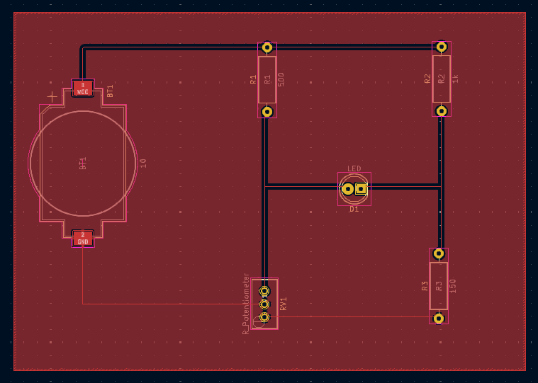
| 보드 크기 | 120 mm × 87.5 mm |
| 배선 폭 | 0.2 mm |
| GND 동박 영역 | 앞면(F.Cu) |
| 전원 | CR2032 전지 홀더 (Battery:BatteryHolder_Keystone_1060_1x2032) |
| 가변저항 | 다회전 트리머 (Potentiometer_THT:Potentiometer_Bourns_3296W_Vertical) |
| LED | 5 mm LED (LED_THT:LED_D5.0mm) |
배치·배선·DRC·거버 출력 방법은 예제 1의 4장과 같다.
시뮬레이션에 필요한 부품과 PCB에 필요한 부품은 다를 수 있다. 이 예제의 전원이 그렇다. 시뮬레이션에는 이상적인 전압원(V1)이, 실제 보드에는 전지 홀더(BT1)가 필요하다.
KiCad에서는 부품 속성(E)의 체크박스로 부품마다 용도를 정한다.
| 부품 | Exclude from simulation | Exclude from board | 결과 |
|---|---|---|---|
V1 (전압원) | ☐ | ☑ | 시뮬레이션에만 쓰이고 PCB에는 나타나지 않는다 |
BT1 (전지) | ☑ | ☐ | PCB에만 쓰이고 시뮬레이션에서는 빠진다 |
D1 (LED), 저항들 | ☐ | ☐ | 둘 다에 쓰인다. D1은 실제 LED 심볼에 시뮬레이션 모델을 붙였다 |
이렇게 하면 회로도를 고친 뒤 Update PCB from Schematic (F8) 을 실행해도 PCB가 그대로 유지된다(회로도와 PCB 일치 검사 결과 불일치 0개).
시뮬레이션은 10 V 전원으로 계산하지만, PCB의 전지 홀더는 CR2032(3 V)용이다. 실제로 보드를 만든다면 전원 전압을 맞추어 저항값을 다시 계산하거나, 9 V 전지 커넥터 같은 다른 전원을 고려한다.
| 증상 | 원인과 해결 |
|---|---|
| 시뮬레이션 시 접지(ground)가 없다는 오류 | Simulation_SPICE:0 기호(또는 GND)가 회로에 없다. 하나 이상 연결한다. |
| 부품에 모델이 없다는 오류 | 해당 부품의 Simulation Model… 에서 모델을 지정하거나, 시뮬레이션에서 제외(Exclude from simulation)한다. |
| 결과가 손 계산과 크게 다름 | 저항 단위를 확인한다. 1k = 1000 Ω, 1m = 0.001 Ω(밀리)이다. 메가옴은 1Meg로 쓴다. |
F8 후 PCB 부품이 사라짐 | 회로도에 없거나 Exclude from board 가 체크된 부품은 PCB에서 삭제된다. 4장의 표를 참고한다. |
| Qty | Value | Footprint | References |
|---|---|---|---|
| 4 | 1K | Adafruit nRF52 Bluefruit Feather rev G:0603-NO | R1, R2, R3, R9 |
| 3 | 10µF | Adafruit nRF52 Bluefruit Feather rev G:0805-NO | C5, C6, C8 |
| 2 | Adafruit nRF52 Bluefruit Feather rev G:1X01_2MM | JP1, JP2 | |
| 2 | Adafruit nRF52 Bluefruit Feather rev G:TESTPOINT_ROUND_2MM | TP3, TP4 | |
| 2 | 0.1uF | Adafruit nRF52 Bluefruit Feather rev G:0603-NO | C10, C11 |
| 2 | 10K | Adafruit nRF52 Bluefruit Feather rev G:0603-NO | R7, R8 |
| 2 | 22pF | Adafruit nRF52 Bluefruit Feather rev G:0603-NO | C1, C2 |
| 2 | 300pF | Adafruit nRF52 Bluefruit Feather rev G:_0603MP | C9, C13 |
| 2 | FIDUCIAL_1MM | Adafruit nRF52 Bluefruit Feather rev G:FIDUCIAL_1MM | FID1, FID3 |
| 2 | KMR2 | Adafruit nRF52 Bluefruit Feather rev G:BTN_KMR2_4.6X2.8 | SW1, SW2 |
| 1 | Adafruit nRF52 Bluefruit Feather rev G:BLUEFRUITLOGO_100MM | U$45 | |
| 1 | Adafruit nRF52 Bluefruit Feather rev G:FEATHERLOGO_MED | U$46 | |
| 1 | Adafruit nRF52 Bluefruit Feather rev G:ADAFRUIT_3.5MM | U$49 | |
| 1 | Adafruit nRF52 Bluefruit Feather rev G:ADAFRUIT_5MM | U$47 | |
| 1 | Adafruit nRF52 Bluefruit Feather rev G:PCBFEAT-REV-040 | U$17 | |
| 1 | 100K | Adafruit nRF52 Bluefruit Feather rev G:0603-NO | R5 |
| 1 | 100k | Adafruit nRF52 Bluefruit Feather rev G:0603-NO | R12 |
| 1 | 10uF | Adafruit nRF52 Bluefruit Feather rev G:0805-NO | C3 |
| 1 | 10uH | Adafruit nRF52 Bluefruit Feather rev G:0805-NO | L2 |
| 1 | 10uf | Adafruit nRF52 Bluefruit Feather rev G:0805-NO | C7 |
| 1 | 1N4148 | Adafruit nRF52 Bluefruit Feather rev G:SOD-323 | D4 |
| 1 | 1nF | Adafruit nRF52 Bluefruit Feather rev G:0603-NO | C12 |
| 1 | 1uF | Adafruit nRF52 Bluefruit Feather rev G:0603-NO | C4 |
| 1 | 2M | Adafruit nRF52 Bluefruit Feather rev G:0603-NO | R6 |
| 1 | 32.768 | Adafruit nRF52 Bluefruit Feather rev G:XTAL3215 | X4 |
| 1 | 4u20317 | Adafruit nRF52 Bluefruit Feather rev G:2X05_1.27MM_BOX_POSTS | X1 |
| 1 | 4u20329 | Adafruit nRF52 Bluefruit Feather rev G:4UCONN_20329_V2 | X3 |
| 1 | 806K | Adafruit nRF52 Bluefruit Feather rev G:0603-NO | R4 |
| 1 | AP2112(3.3V) | Adafruit nRF52 Bluefruit Feather rev G:SOT23-5 | U2 |
| 1 | BAT | Adafruit nRF52 Bluefruit Feather rev G:SOLDERJUMPER_CLOSEDWIRE | SJ2 |
| 1 | BLUE | Adafruit nRF52 Bluefruit Feather rev G:CHIPLED_0805_NOOUTLINE | D2 |
| 1 | CP2104 | Adafruit nRF52 Bluefruit Feather rev G:QFN24_4MM_SMSC | U4 |
| 1 | DMG3415U-7 | Adafruit nRF52 Bluefruit Feather rev G:SOT23-R | Q3 |
| 1 | FEATHERWING_NODIM | Adafruit nRF52 Bluefruit Feather rev G:FEATHERWING_NODIM | MS1 |
| 1 | FRST | Adafruit nRF52 Bluefruit Feather rev G:PAD-1.5X2.0 | TP2 |
| 1 | JSTPH | Adafruit nRF52 Bluefruit Feather rev G:JSTPH2 | X2 |
| 1 | MBR120 | Adafruit nRF52 Bluefruit Feather rev G:SOD-123 | D5 |
| 1 | MCP73831T-2ACI/OT | Adafruit nRF52 Bluefruit Feather rev G:SOT23-5 | U3 |
| 1 | MDBT42 | Adafruit nRF52 Bluefruit Feather rev G:BLE_MODULE_RAYTAC_MDBT42 | U1 |
| 1 | ORANGE | Adafruit nRF52 Bluefruit Feather rev G:CHIPLED_0805_NOOUTLINE | CHG0 |
| 1 | RED | Adafruit nRF52 Bluefruit Feather rev G:CHIPLED_0805_NOOUTLINE | D1 |
sckim/KiCAD
휘트스톤 브리지(Wheatstone Bridge)는 저항 4개로 두 개의 분압기를 만들고, 두 중간점의 전압 차이로 저항의 균형 여부를 판단하는 회로이다. 이 예제에서는 예제 1의 흐름(회로도 → PCB)에 더해 KiCad에 내장된 SPICE 시뮬레이터(ngspice) 로 회로를 먼저 계산해 보는 방법을 익힌다.

sckim/KiCAD
휘트스톤 브리지(Wheatstone Bridge)는 저항 4개로 두 개의 분압기를 만들고, 두 중간점의 전압 차이로 저항의 균형 여부를 판단하는 회로이다. 이 예제에서는 예제 1의 흐름(회로도 → PCB)에 더해 KiCad에 내장된 SPICE 시뮬레이터(ngspice) 로 회로를 먼저 계산해 보는 방법을 익힌다.

sckim/KiCAD
휘트스톤 브리지(Wheatstone Bridge)는 저항 4개로 두 개의 분압기를 만들고, 두 중간점의 전압 차이로 저항의 균형 여부를 판단하는 회로이다. 이 예제에서는 예제 1의 흐름(회로도 → PCB)에 더해 KiCad에 내장된 SPICE 시뮬레이터(ngspice) 로 회로를 먼저 계산해 보는 방법을 익힌다.

sckim/KiCAD
휘트스톤 브리지(Wheatstone Bridge)는 저항 4개로 두 개의 분압기를 만들고, 두 중간점의 전압 차이로 저항의 균형 여부를 판단하는 회로이다. 이 예제에서는 예제 1의 흐름(회로도 → PCB)에 더해 KiCad에 내장된 SPICE 시뮬레이터(ngspice) 로 회로를 먼저 계산해 보는 방법을 익힌다.

sckim/KiCAD
휘트스톤 브리지(Wheatstone Bridge)는 저항 4개로 두 개의 분압기를 만들고, 두 중간점의 전압 차이로 저항의 균형 여부를 판단하는 회로이다. 이 예제에서는 예제 1의 흐름(회로도 → PCB)에 더해 KiCad에 내장된 SPICE 시뮬레이터(ngspice) 로 회로를 먼저 계산해 보는 방법을 익힌다.

sckim/KiCAD
휘트스톤 브리지(Wheatstone Bridge)는 저항 4개로 두 개의 분압기를 만들고, 두 중간점의 전압 차이로 저항의 균형 여부를 판단하는 회로이다. 이 예제에서는 예제 1의 흐름(회로도 → PCB)에 더해 KiCad에 내장된 SPICE 시뮬레이터(ngspice) 로 회로를 먼저 계산해 보는 방법을 익힌다.


wizarddata/Blue-Wizard-Mod
Bluetooth Controller for the Kinesis Advantage line of keyboards using the BlueMicro firmware

ElectronicCats/Minino
Minino is an original multiprotocol and multiband board made for sniffing, communicating, and attacking IoT devices. It was designed as a mini Cat that integrates the powerful ESP32C6, GPS, microSD and OLED.


It measures 50.8 × 22.9 mm and has 2 copper layers, 1.6 mm thick.
54 parts, built around the CP2104EK, MDBT42Q, MCP73831T-2ACI/OT-HXY and DMG3415U-7. The full list of its parts is on this page, with links to each part's symbol and footprint where PCBKit's library has them.
From the sckim/KiCAD repository on GitHub, at the commit this page was made from: the board is Applications/Adafruit_nRF52_Bluefruit/Adafruit nRF52 Bluefruit Feather rev G.kicad_pcb and its schematic 10_Simple_LED/Simple_LED.kicad_sch. PCBKit opens the board in the browser, with nothing to install.
Its repository publishes it under the GPL-3.0 licence: you may reuse it on that licence's terms (keep the author's notice, and for a copyleft licence share your changes alike).