2 layers117 × 64 mm

 schuyler4/USB_Curve_Tracer5
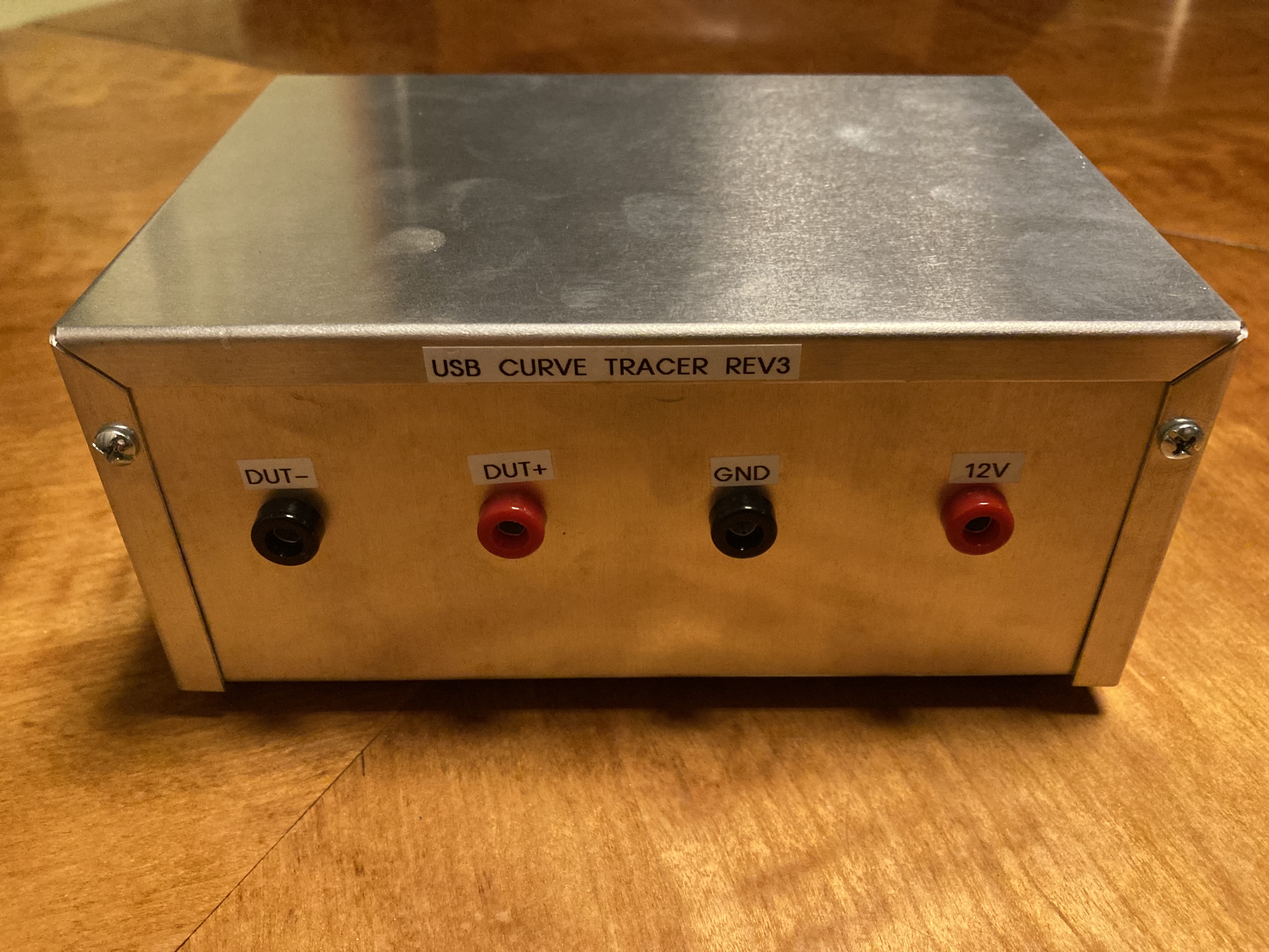
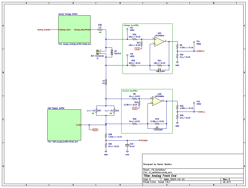
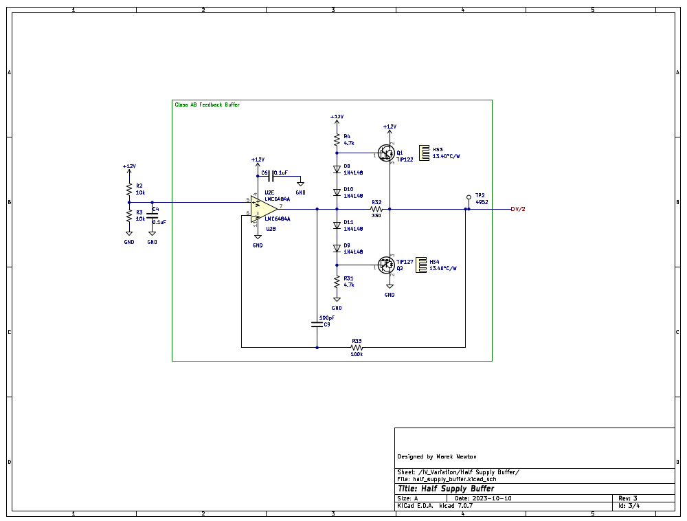
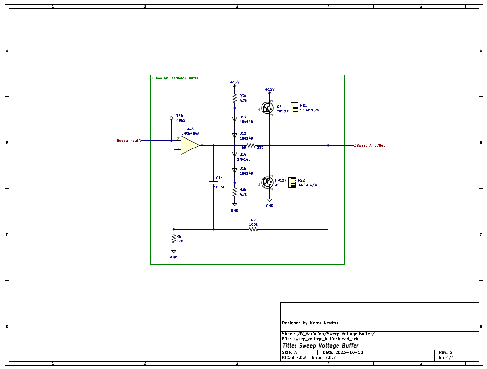
This is a curve tracer design.
USB curve tracer is an open-source printed circuit board by schuyler4, from the schuyler4/USB_Curve_Tracer repository on GitHub, published under the MIT licence. It is a 2-layer board of 138 × 77 mm with 91 parts on 66 nets, routed with 616 tracks and 62 vias.
It is built around the LMC6484AIM, MCP3204-CI/P and MCP4911-E/P, with the LM385BZ-2.5, BZX79-C2V4,113 and TIP122 among its other parts. Its parts include 37 resistors, 16 diodes, 11 capacitors, 4 ICs and 4 transistors. It belongs with the AVR (ATmega, ATtiny) boards of this library.


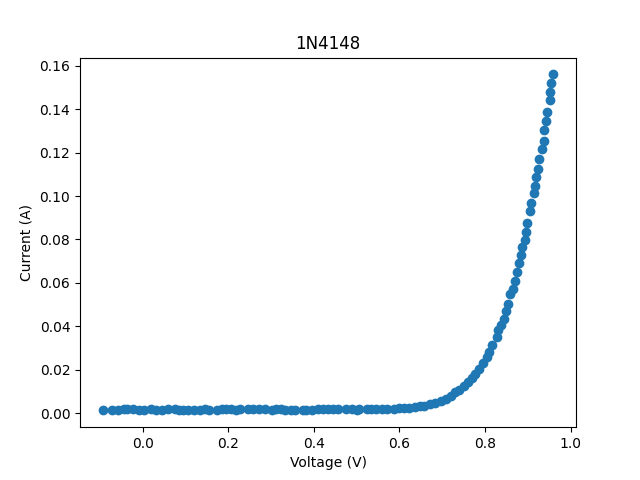
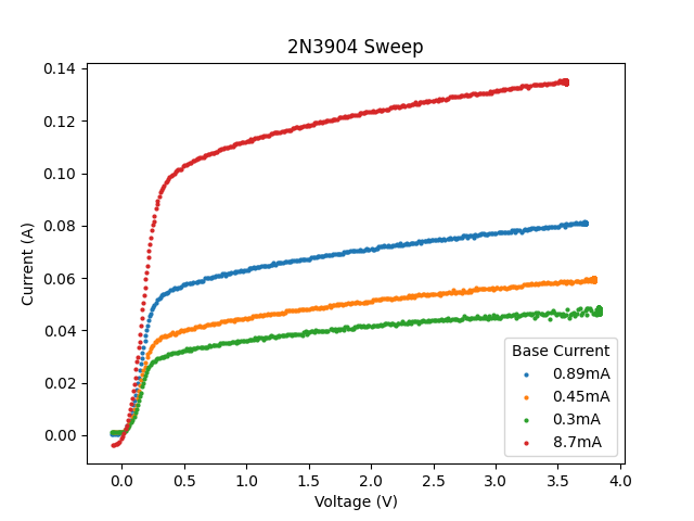
Below is an example 1N4148 diode sweep and a 2N3904 BJT sweep. Short of curve tracing with a different system and doing a comparison, there is not really a good way to verify if these are correct. However, the general shape of the curves does look right. There is clearly some offset error for the red trace of the 2N3904 sweep.
| Qty | Value | Footprint | References |
|---|---|---|---|
| 11 | 10k | Resistor_THT:R_Axial_DIN0207_L6.3mm_D2.5mm_P7.62mm_Horizontal | R1, R2, R3, R6, R7, R22, R24, R25, R26, R27, R33 |
| 8 | 1N4148 | Diode_THT:D_DO-35_SOD27_P7.62mm_Horizontal | D8, D9, D10, D11, D12, D13, D14, D15 |
| 6 | 0.1uF | Capacitor_THT:C_Disc_D6.0mm_W2.5mm_P5.00mm | C1, C2, C4, C5, C6, C10 |
| 6 | 4952 | TestPoint:TestPoint_THTPad_D2.5mm_Drill1.2mm | TP1, TP2, TP3, TP4, TP5, TP6 |
| 4 | 10k+/-0.1% | Resistor_THT:R_Axial_DIN0207_L6.3mm_D2.5mm_P7.62mm_Horizontal | R14, R15, R16, R17 |
| 4 | 13.40°C/W | Library:HSINK_531002B02500G | HS1, HS2, HS3, HS4 |
| 4 | 1k+/-0.1% | Resistor_THT:R_Axial_DIN0207_L6.3mm_D2.5mm_P7.62mm_Horizontal | R8, R18, R20, R28 |
| 4 | 4.7k | Resistor_THT:R_Axial_DIN0207_L6.3mm_D2.5mm_P7.62mm_Horizontal | R4, R31, R34, R35 |
| 4 | M3 | MountingHole:MountingHole_3.2mm_M3_Pad_Via | H1, H2, H3, H4 |
| 3 | 1k | Resistor_THT:R_Axial_DIN0207_L6.3mm_D2.5mm_P7.62mm_Horizontal | R9, R30, R32 |
| 3 | 3.83k+/-0.1% | Resistor_THT:R_Axial_DIN0207_L6.3mm_D2.5mm_P7.62mm_Horizontal | R5, R23, R29 |
| 3 | BZX79-C2V4 | Diode_THT:D_DO-35_SOD27_P7.62mm_Horizontal | D3, D4, D5 |
| 2 | 1+/-1% | Resistor_SMD:R_2512_6332Metric_Pad1.40x3.35mm_HandSolder | R13, R37 |
| 2 | 100pF | Capacitor_THT:C_Disc_D6.0mm_W2.5mm_P5.00mm | C9, C11 |
| 2 | 10nF | Capacitor_THT:C_Disc_D6.0mm_W2.5mm_P5.00mm | C7, C8 |
| 2 | 11.8k+/-0.1% | Resistor_THT:R_Axial_DIN0207_L6.3mm_D2.5mm_P7.62mm_Horizontal | R10, R19 |
| 2 | 619 | Resistor_THT:R_Axial_DIN0207_L6.3mm_D2.5mm_P7.62mm_Horizontal | R11, R12 |
| 2 | TIP122 | Package_TO_SOT_THT:TO-220-3_Vertical | Q1, Q3 |
| 2 | TIP127 | Package_TO_SOT_THT:TO-220-3_Vertical | Q2, Q4 |
| 1 | 1.5 | Resistor_SMD:R_2512_6332Metric_Pad1.40x3.35mm_HandSolder | R36 |
| 1 | 10uF | Capacitor_THT:C_Disc_D6.0mm_W2.5mm_P5.00mm | C3 |
| 1 | 14k | Resistor_THT:R_Axial_DIN0207_L6.3mm_D2.5mm_P7.62mm_Horizontal | R21 |
| 1 | 1A | Fuse:Fuse_1206_3216Metric_Pad1.42x1.75mm_HandSolder | F2 |
| 1 | 1N5817 | Diode_THT:D_DO-41_SOD81_P10.16mm_Horizontal | D16 |
| 1 | 3A | Fuse:Fuse_1206_3216Metric_Pad1.42x1.75mm_HandSolder | F1 |
| 1 | Arduino_Nano_v3.x | Module:Arduino_Nano | A1 |
| 1 | DUT Connector | TerminalBlock_Phoenix:TerminalBlock_Phoenix_MKDS-1,5-2-5.08_1x02_P5.08mm_Horizontal | J1 |
| 1 | LM385BZ-2.5 | Package_TO_SOT_THT:TO-92_Inline | U4 |
| 1 | LMC6484A | Package_DIP:DIP-14_W7.62mm | U2 |
| 1 | MCP3204 | Package_DIP:DIP-14_W7.62mm | U3 |
| 1 | MCP4911 | Package_DIP:DIP-8_W7.62mm | U1 |
| 1 | Power Input | TerminalBlock_Phoenix:TerminalBlock_Phoenix_MKDS-1,5-2-5.08_1x02_P5.08mm_Horizontal | J2 |
| 1 | SA13A | Diode_THT:D_DO-15_P10.16mm_Horizontal | D1 |
| 1 | SA13CA | Diode_THT:D_DO-15_P10.16mm_Horizontal | D2 |
| 1 | WP7113ID | LED_THT:LED_D5.0mm | D7 |
| 1 | WP7113SGD | LED_THT:LED_D5.0mm | D6 |


ryomuk/tangnano20k-vectrex
Tang Nano 20K top level module for Dar's Vectrex


RidhaBouyahi/Motor-Control-And-Dashboard-PCB
This Dashboard PCB is developed to get data (position,temperature...) from sensors, control actuators and Dc Motor direction and speed control using PWM .


It measures 138 × 77 mm and has 2 copper layers, 1.6 mm thick.
91 parts, built around the LMC6484AIM, MCP3204-CI/P, MCP4911-E/P and LM385BZ-2.5. The full list of its parts is on this page, with links to each part's symbol and footprint where PCBKit's library has them.
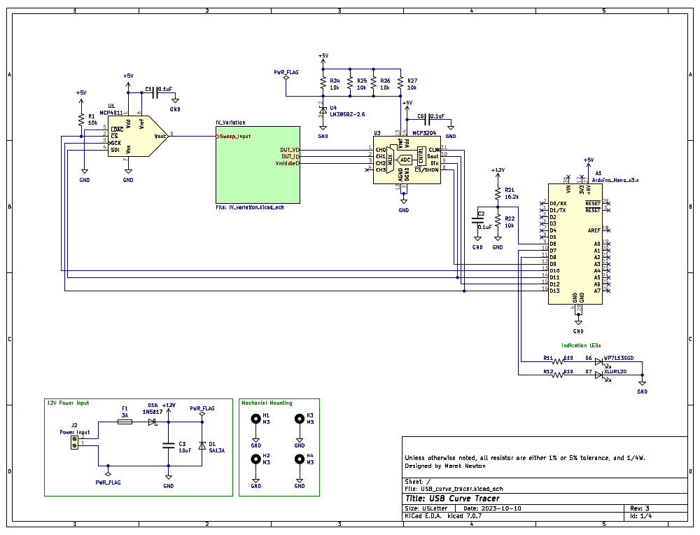
From the schuyler4/USB_Curve_Tracer repository on GitHub, at the commit this page was made from: the board is electronics/rev3/ecad/USB_curve_tracer.kicad_pcb and its schematic electronics/rev2/ecad/IV_variation.kicad_sch. PCBKit opens the board in the browser, with nothing to install.
Its repository publishes it under the MIT licence: you may reuse it on that licence's terms (keep the author's notice, and for a copyleft licence share your changes alike).