2 layers216.9 × 86.8 mm
Sweepv2
davidphilipbarr/Sweep
Sweep - a small promicro based keyboard inspired by the Ferris.
51 parts2.1k

 schenkzoola/PowerBrigand16
A kit that allows you to build a high power 12v supply from a surplus HP server power supply.
PowerBrigand is an open-source printed circuit board by schenkzoola, from the schenkzoola/PowerBrigand repository on GitHub. It is a 2-layer board of 90 × 100 mm with 51 parts on 54 nets, routed with 258 tracks and 39 vias.
Its parts include 15 resistors, 7 connectors, 5 switches, 4 diodes and 4 fuses. It belongs with the AVR (ATmega, ATtiny) boards of this library.
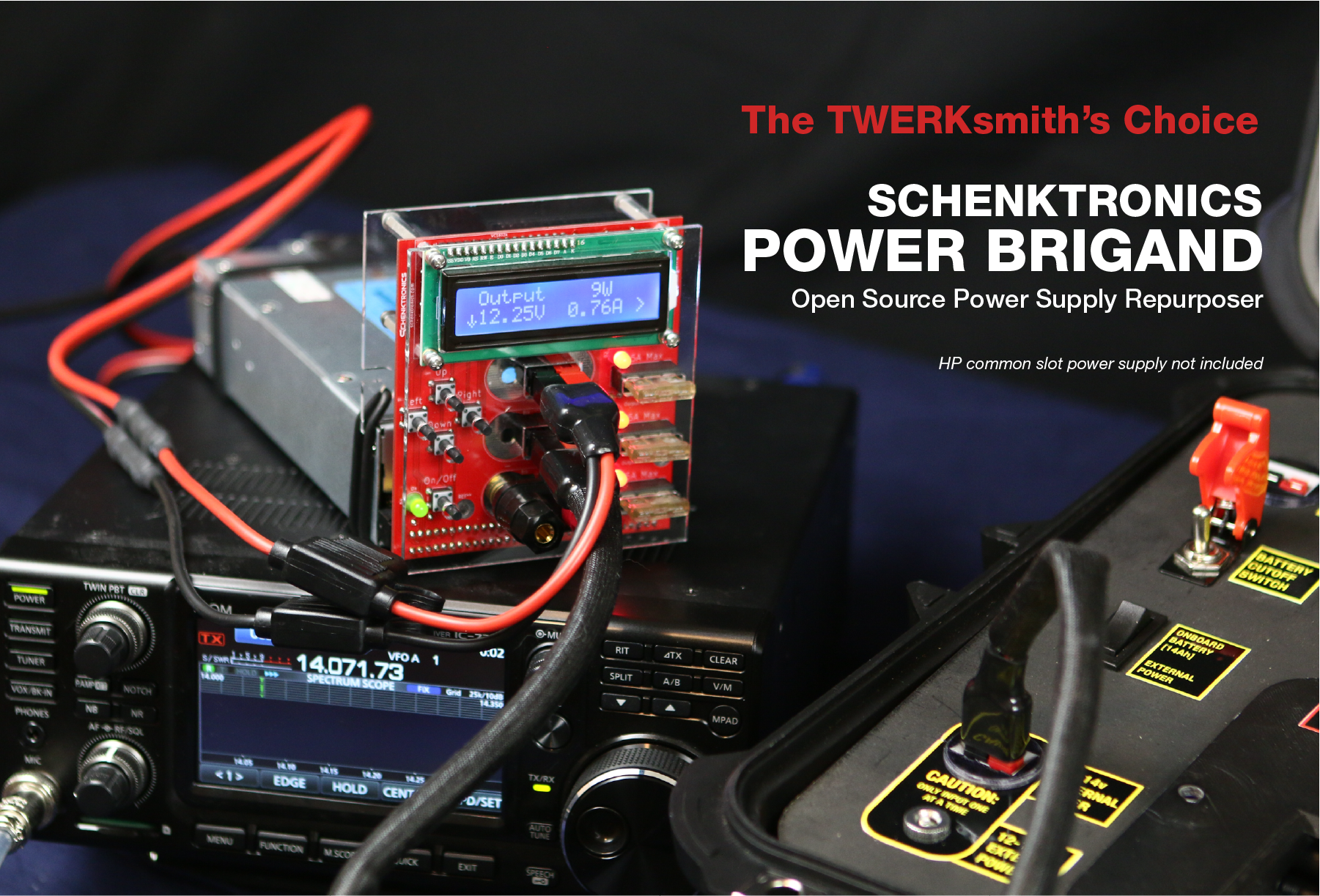
Well, you can build one yourself from the source files here, or better yet, you can join the waitlist for a kit from my Tindie store below: https://www.tindie.com/products/schenktronics/power-brigand/ The parts for the first batch of kits have been ordered!
Power Brigand is a module that attaches to HP common slot power supplies that are normally used in servers. It has connectors and/or binding posts to bring 12v power to your devices. It also has controls which allow you to turn the power supply on and off, as well as display parameters such as voltage, current, and temperature from the i2c bus on the power supply.
After leaving the cryptocurrency mining scene, I had quite a few of these power supplies. They are plentiful on eBay, and therefore inexpensive. I felt it wasn't worth my time trying to sell them, and wanted a way to repurpose them. I was unimpressed with the typical breakout board available from eBay and Aliexpress.
I found a few resources to start with. This one discussed the supply, and compared it to a similar Murata power supply.
The best source of information I found was this github repo where the author, DrTune, reverse engineered a power supply by decompiling the firmware from the internal microcontroller. DrTune created some sample python code to read and write data to and from the I2C bus. This gave me information on which registers to query for the data.
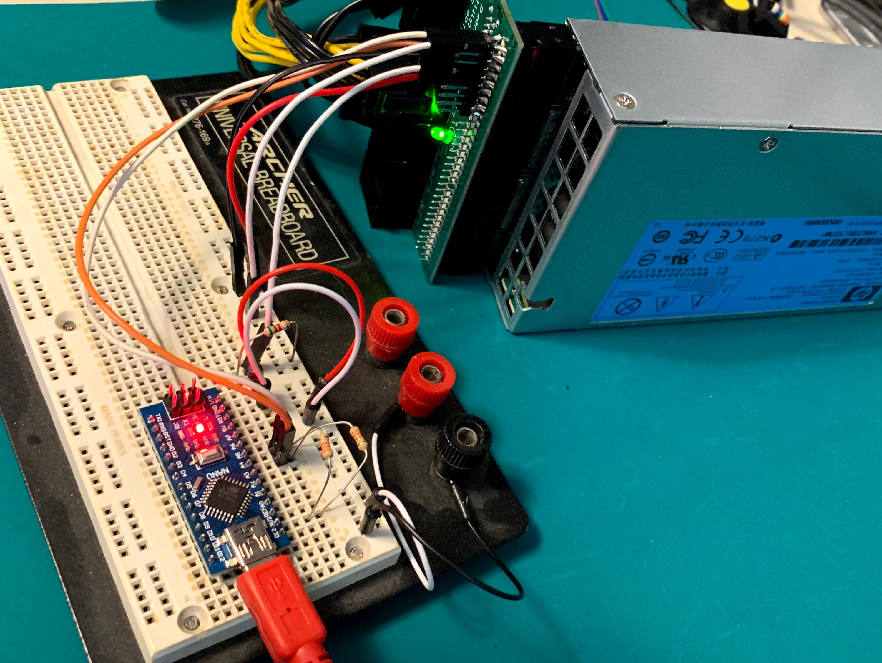
Using an arduino nano, a bus pirate, and DrTune's python code as a guide, I was able to successfully read the I2C bus. This encouraged me to create a PCB with an LCD, output terminals, and fuses.
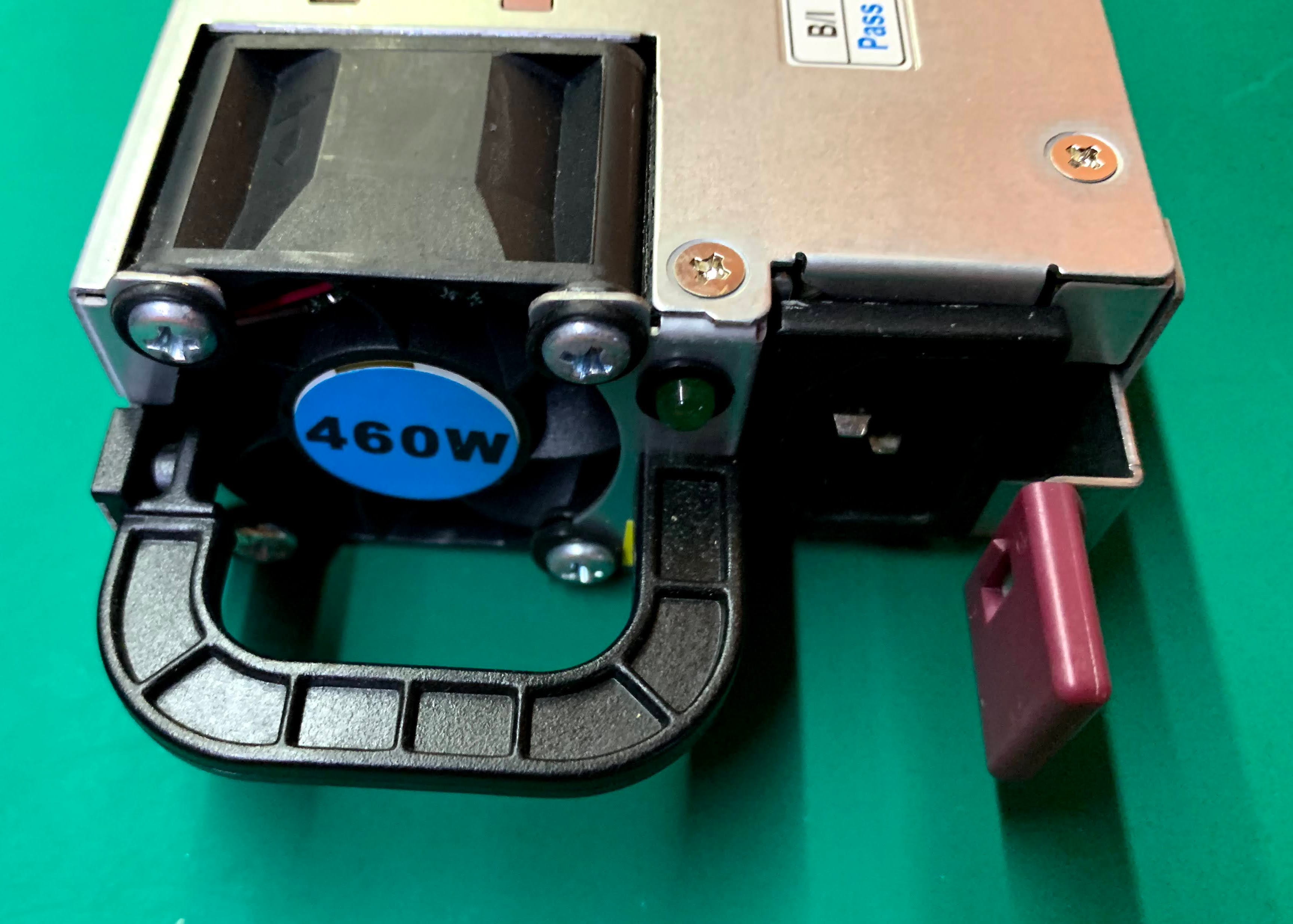
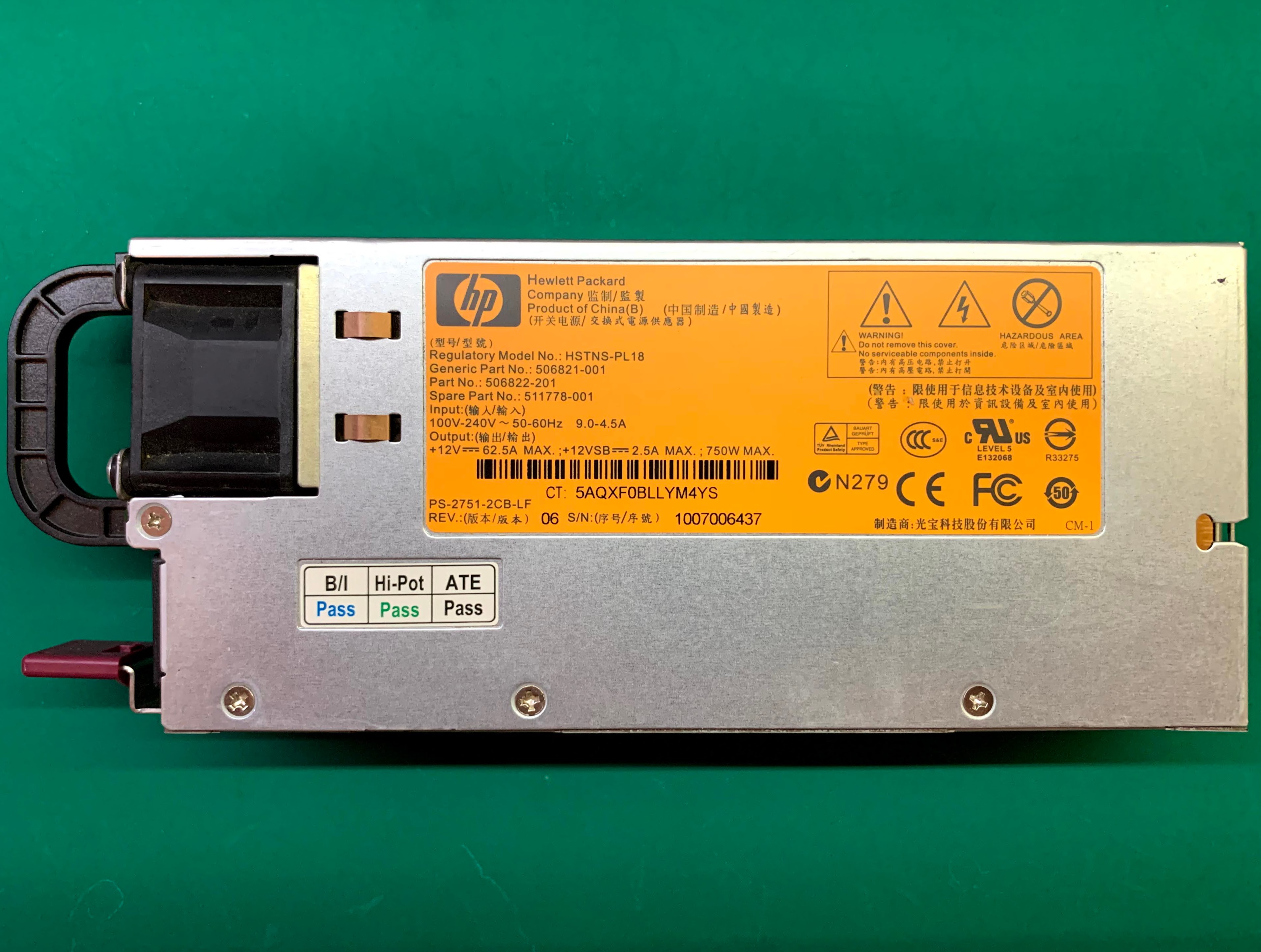
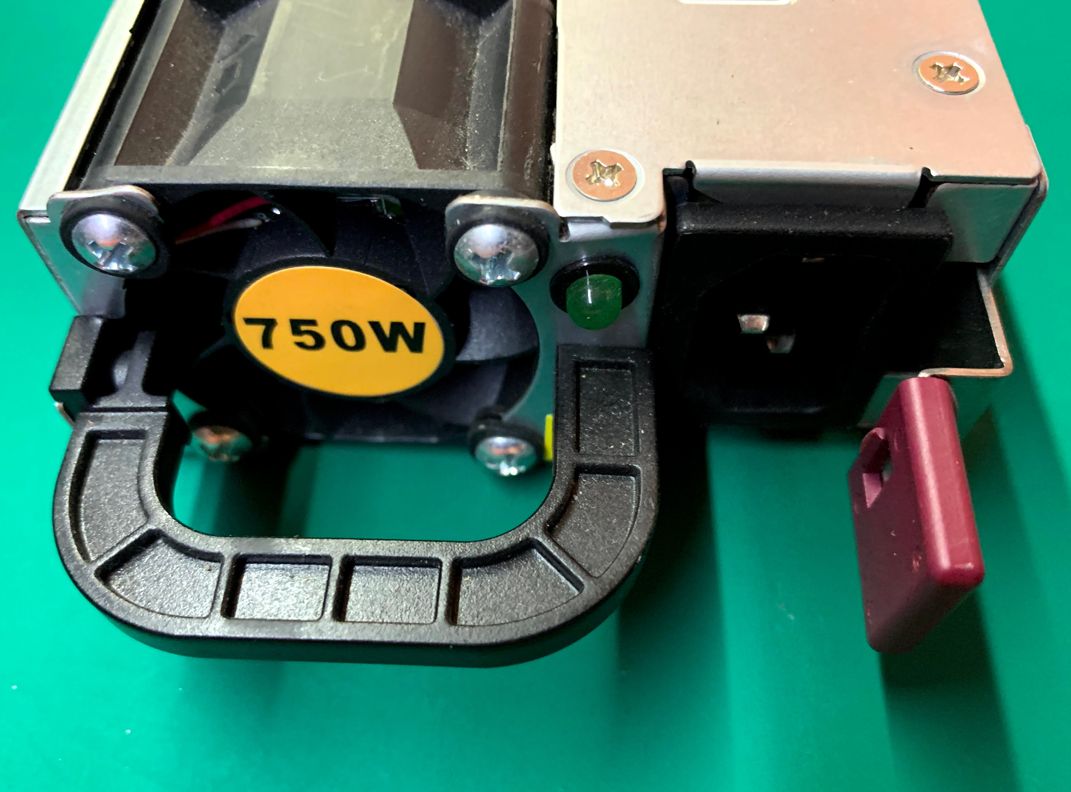
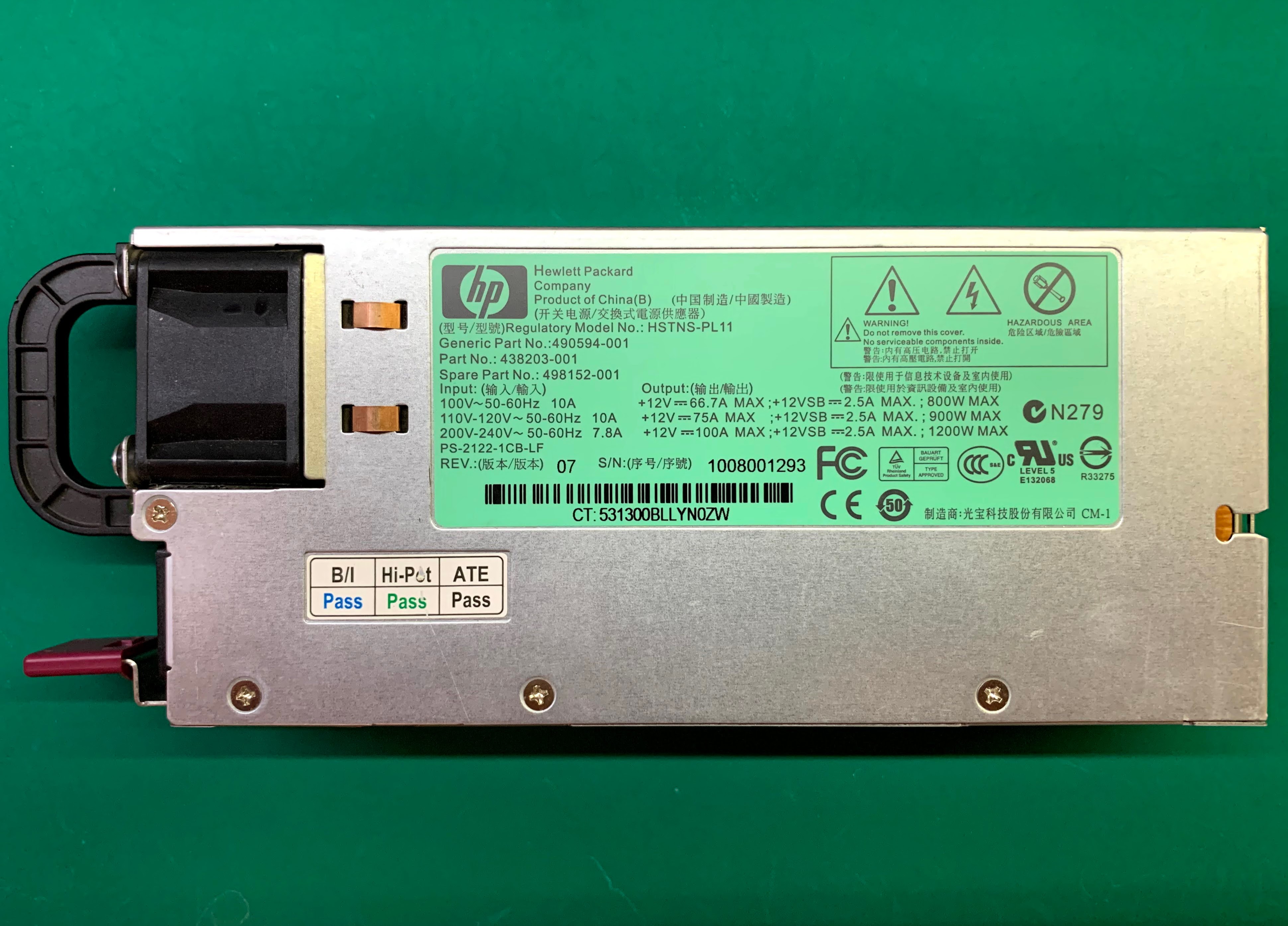
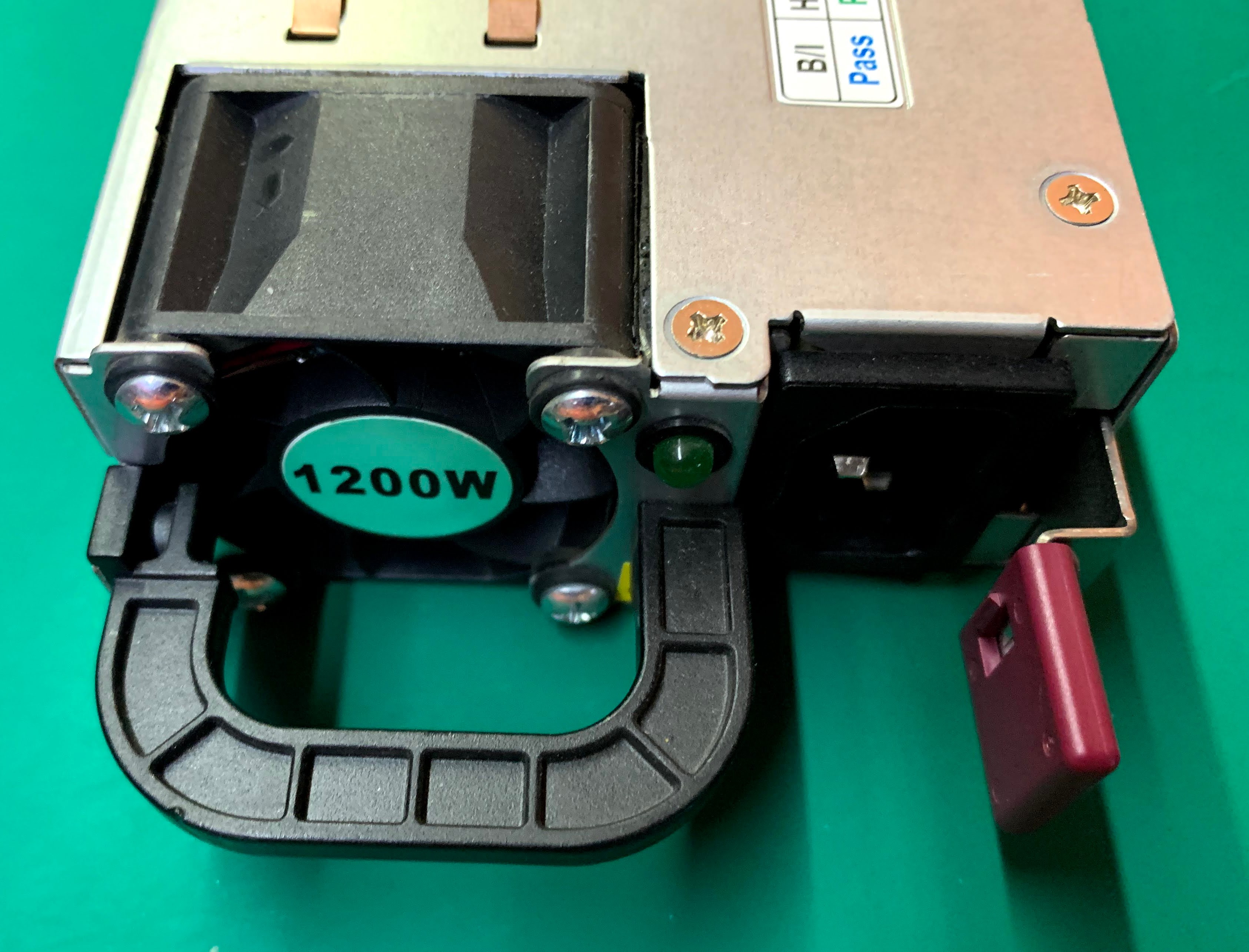
This is the heart of the Power Brigand, it won't work without one. There are at least four commonly available versions of these power supplies: 460W, 750W, and two different 1200W versions.
This is the smallest of the power supplies, and the quietest. Despite its small size, it is capable of producing 38.3A. My testing has shown that this has the quietest fan, and the most sensitive current measurement capability.
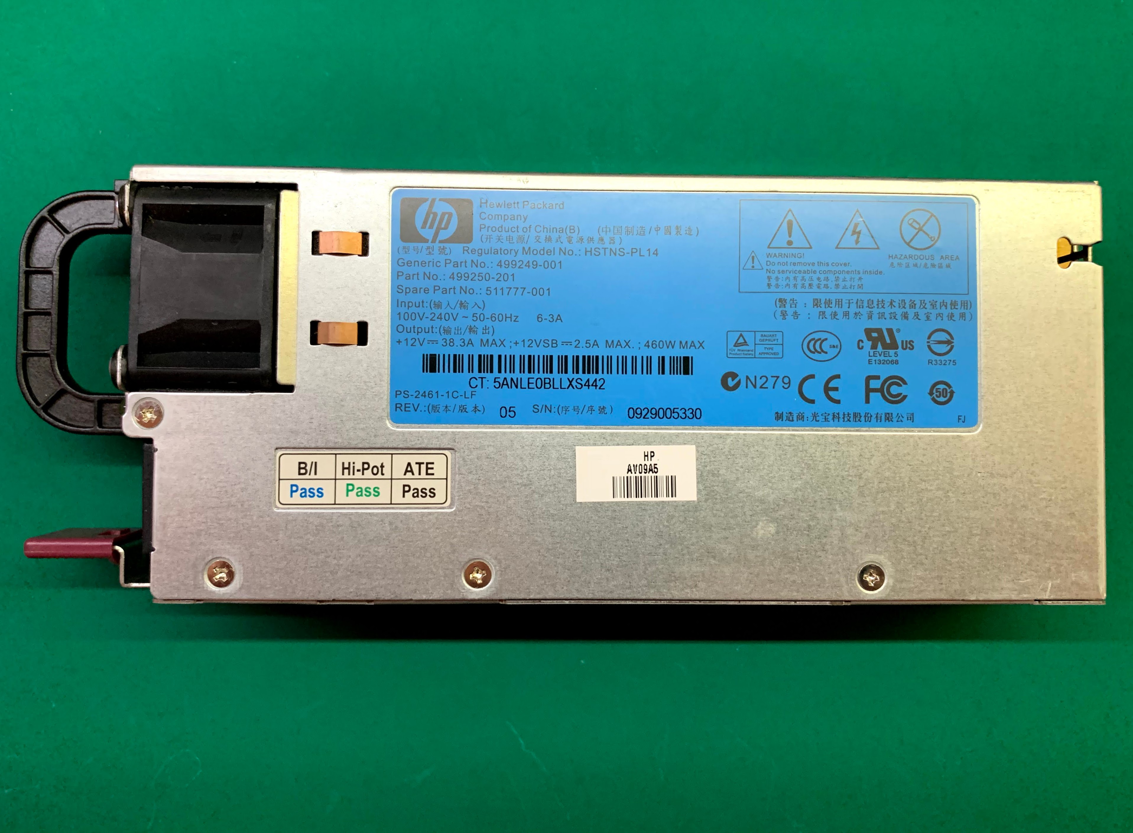
This is the middle size power supply. It can produce 62.5A. Its fan is noisier than the 460W, and the minimum current it can accurately display is about 5A.
There are two 1200W power supplies, one is higher efficiency than the other. They are sensitive to the input voltage. At 120V they can only produce 75A. They require a 200V-240V power source to produce their full capability of 100A. These power supplies also have a minimum accurate current display of about 5A, and they typically have noisier fans than the others.
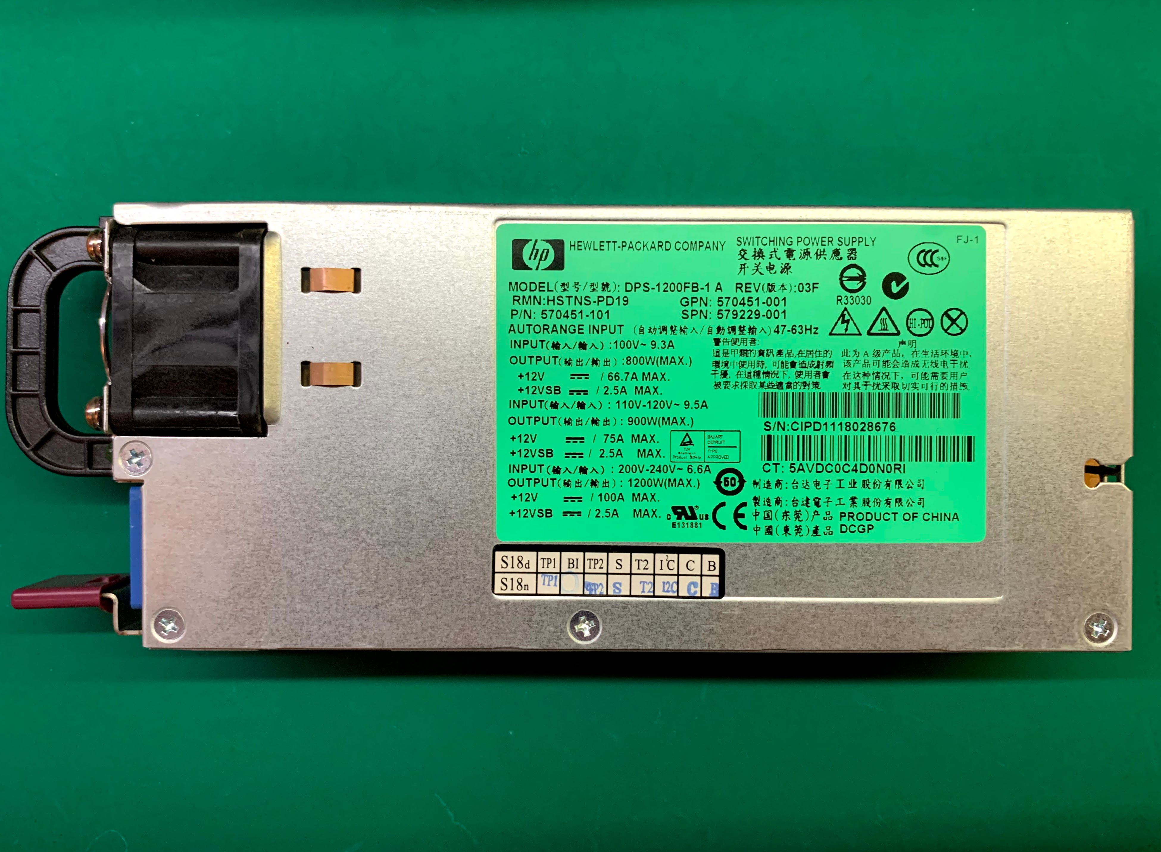
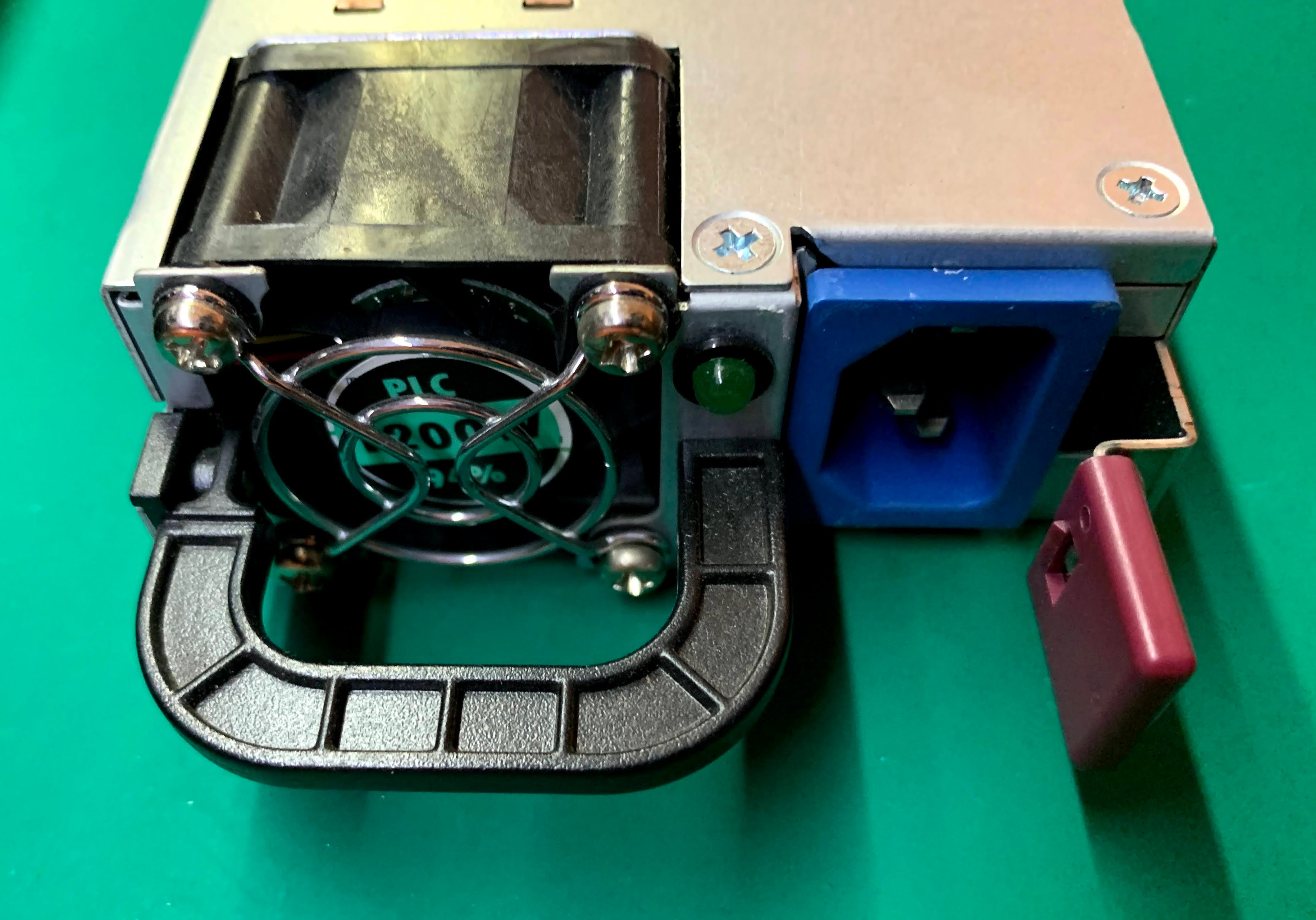
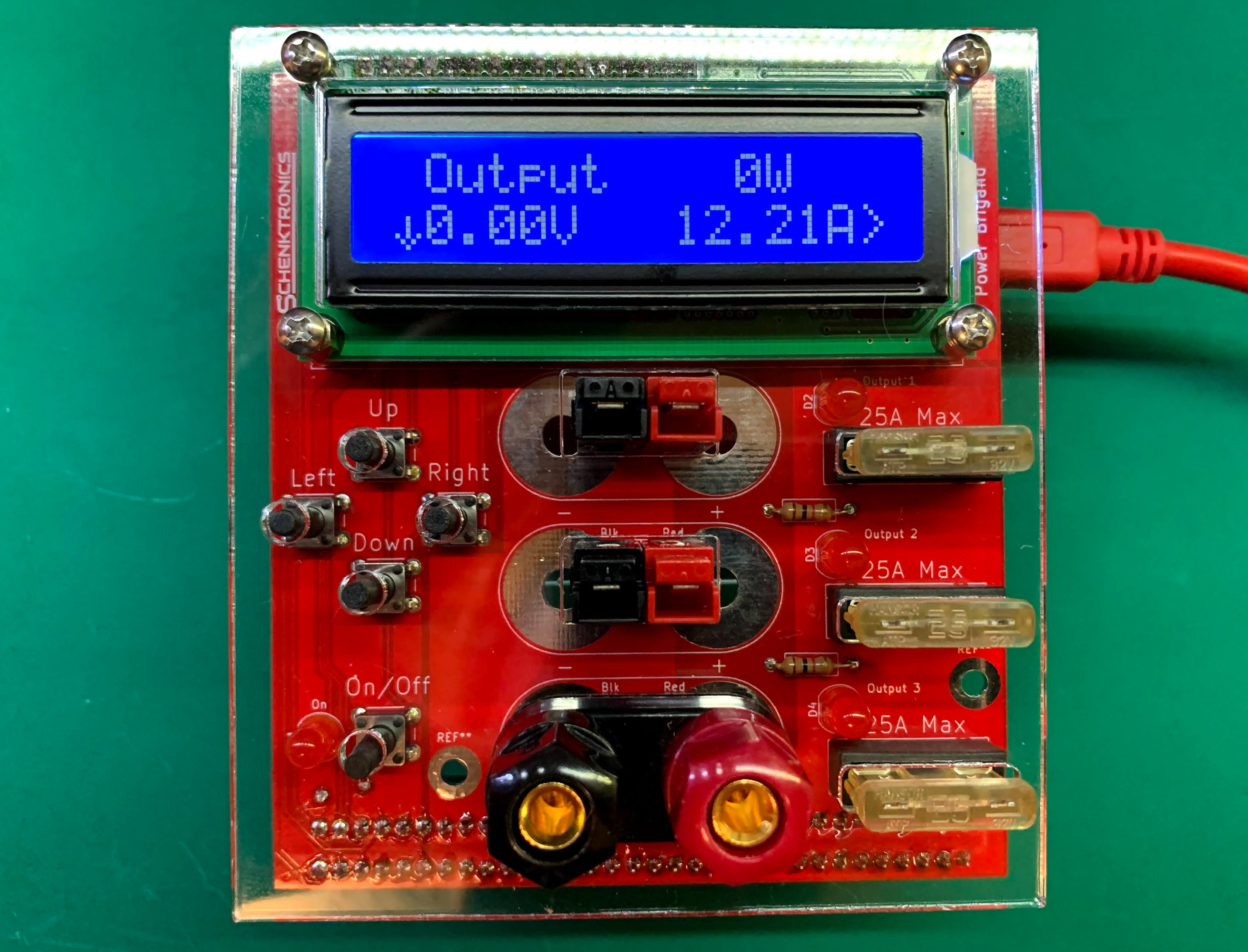
The power brigand consists of a main PCB which integrates the edge card connector, fuses, buttons, LED's, LCD, Arduino Nano, and other supporting components.
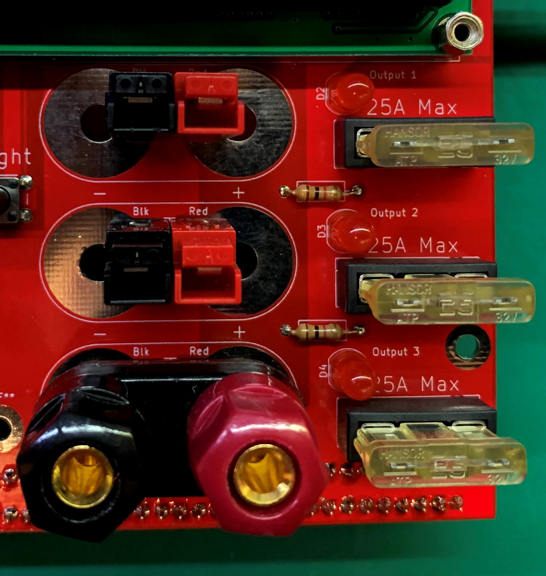
There are three 25A fused outputs, for 75A total output capability. Each fuse has an LED next to it to indicate whether there is voltage after the fuse. If one of the LED's is not lit, there is a good chance that fuse is blown. The fuse holders are designed to accommodate standard automotive blade style fuses.
The outputs can be configured with either binding posts, or Anderson powerpole connectors. A typical configuration would have two sets of powerpole connectors and one pair of binding posts.
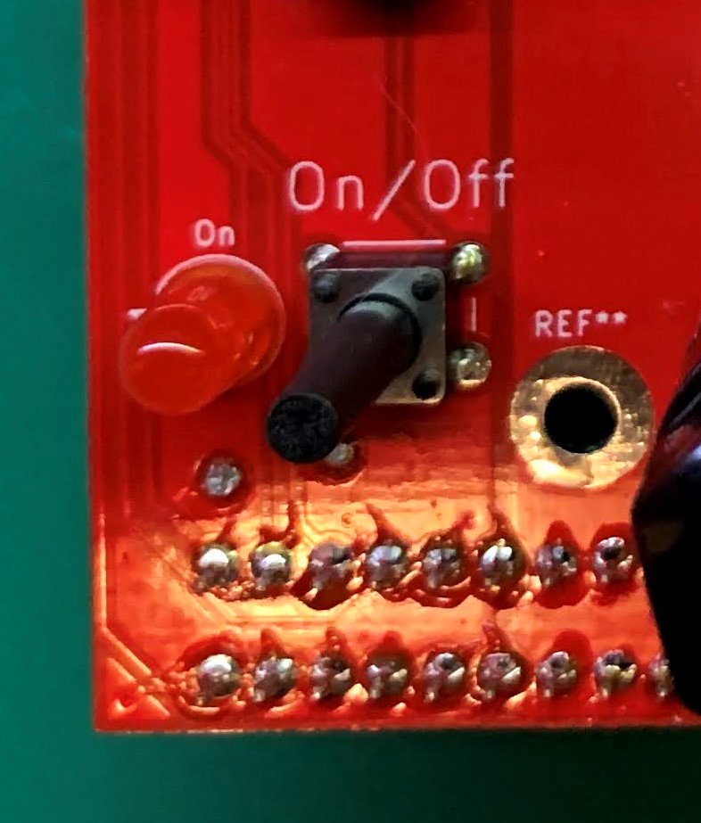
On the lower left, there is a power button. Press this button once to turn on the outputs. Hold this button to turn off the outputs. The LED next to the power button will illuminate when the outputs are commanded to turn on.
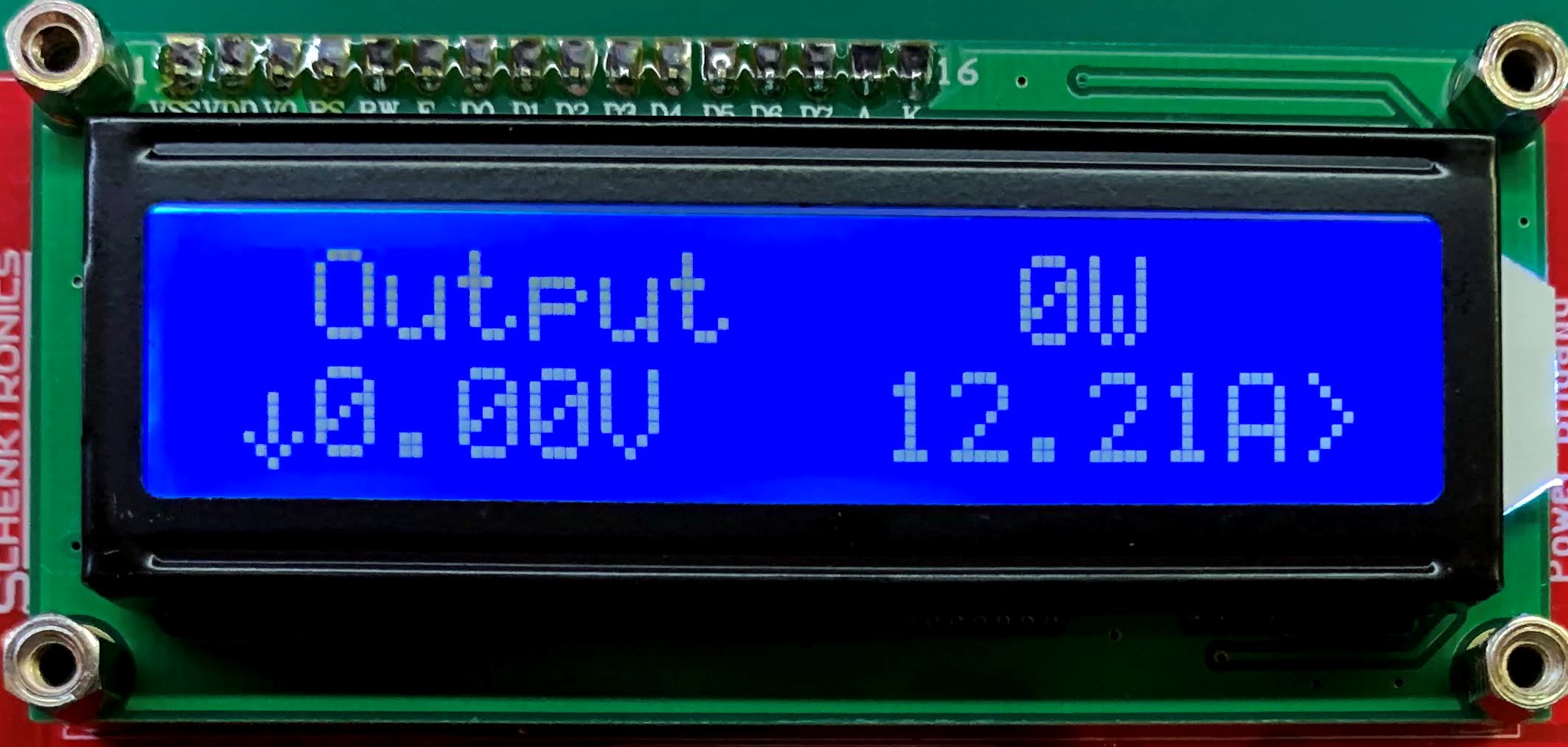
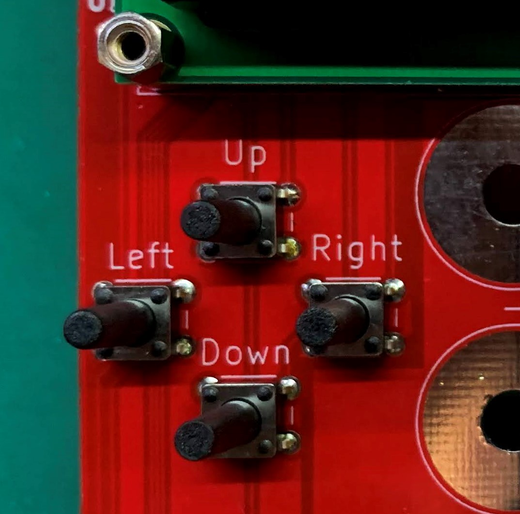
The LCD is where the information is displayed. There are four push buttons just below the left of the LCD. If you see an arrow on the display, it indicates you can push one of these four buttons to navigate. If you see an arrow pointing up, that means you can press the "up" button. If you see an arrow pointing to the right, that means you can press the "right" button, and so on.
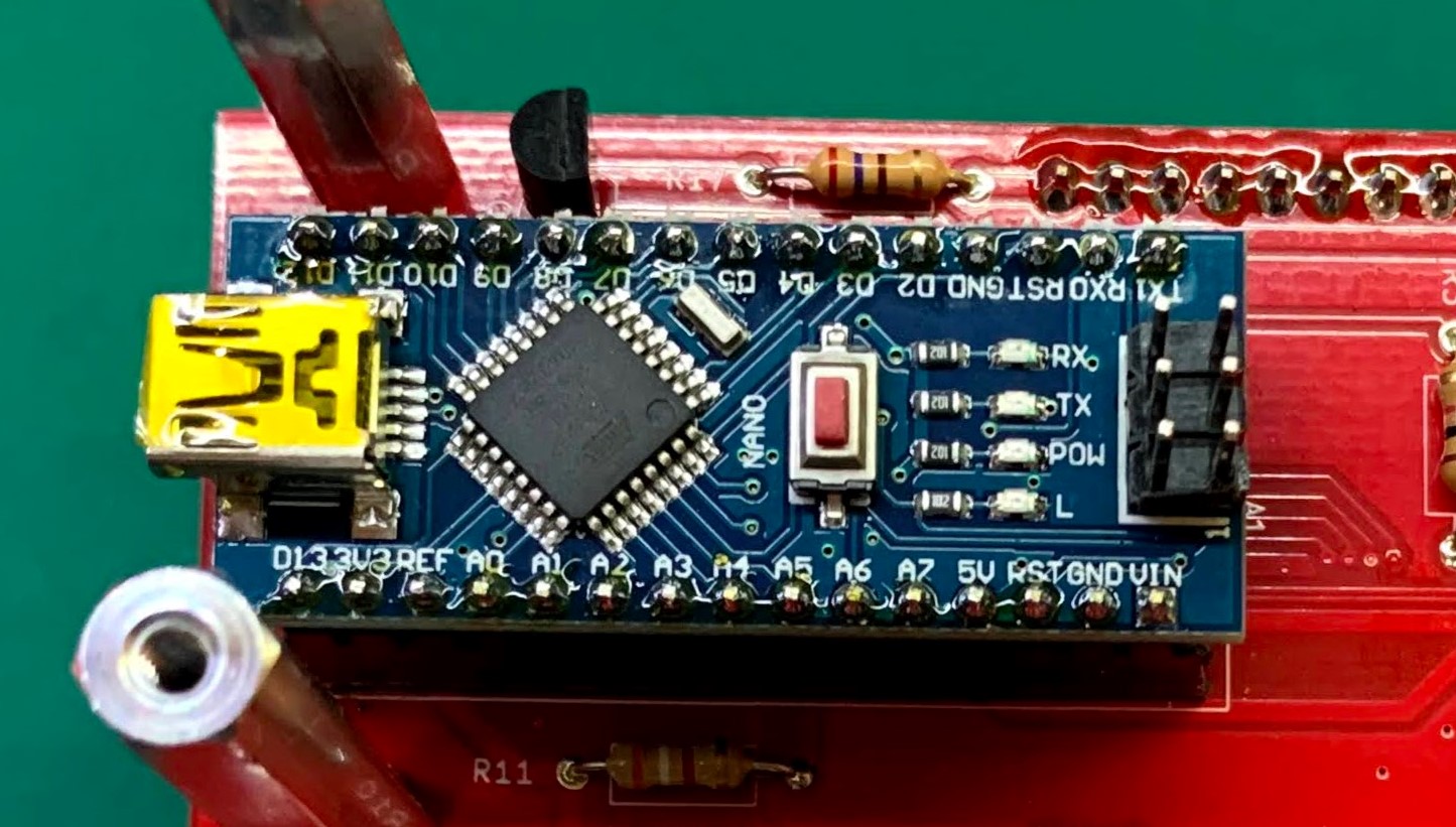
The Arduino Nano compatible module is the "brains" of the unit. It reads the I2C bus on the power supply, commands it on and off, writes data to the LCD, and handles the buttons. The software is written and C and can easily be modified using the Arduino IDE.

This work is licensed under a Creative Commons Attribution-NonCommercial-ShareAlike 4.0 International License.
| Qty | Value | Footprint | References |
|---|---|---|---|
| 13 | 3.9k | Resistor_THT:R_Axial_DIN0207_L6.3mm_D2.5mm_P10.16mm_Horizontal | R1, R2, R4, R5, R6, R7, R8, R9, R10, R11, R12, R13, R14 |
| 3 | 25A Max | _NTSFootprints:FuseHolder_Keystone_3557-2 | F2, F3, F4 |
| 3 | Anderson | _NTSFootprints:ASMPV45-1X2-RK | J5, J6, J7 |
| 3 | Binding Post | _NTSFootprints:BindingPost_Keystone_7019 | J2, J3, J4 |
| 2 | 100nF | Capacitor_THT:C_Disc_D5.0mm_W2.5mm_P5.00mm | C1, C2 |
| 2 | 2N3904 | Package_TO_SOT_THT:TO-92_Inline_Wide | Q1, Q2 |
| 2 | LOGO | _NTSFootprints:SchentronicsLogo | G***, G*** |
| 1 | 0.5A Polyfuse | Fuse:Fuse_Bourns_MF-RHT100 | F1 |
| 1 | 1k | Resistor_THT:R_Axial_DIN0207_L6.3mm_D2.5mm_P10.16mm_Horizontal | R3 |
| 1 | 270 | Resistor_THT:R_Axial_DIN0207_L6.3mm_D2.5mm_P10.16mm_Horizontal | R17 |
| 1 | 64Pin Edge Card | _NTSFootprints:FCI_10046971-001LF | J1 |
| 1 | Arduino_Nano_v3.x | _NTSFootprints:Arduino_Nano | A1 |
| 1 | Contrast | Potentiometer_THT:Potentiometer_Bourns_3386P_Vertical | RV1 |
| 1 | Down | Button_Switch_THT:SW_PUSH_6mm_H13mm | SW3 |
| 1 | LOGO | _NTSFootprints:schenktronics.com_OSHW_Logo_11x11mm | G*** |
| 1 | Left | Button_Switch_THT:SW_PUSH_6mm_H13mm | SW4 |
| 1 | On | LED_THT:LED_D5.0mm | D1 |
| 1 | On/Off | Button_Switch_THT:SW_PUSH_6mm_H13mm | SW1 |
| 1 | Output 1 | LED_THT:LED_D5.0mm | D2 |
| 1 | Output 2 | LED_THT:LED_D5.0mm | D3 |
| 1 | Output 3 | LED_THT:LED_D5.0mm | D4 |
| 1 | Right | Button_Switch_THT:SW_PUSH_6mm_H13mm | SW5 |
| 1 | Up | Button_Switch_THT:SW_PUSH_6mm_H13mm | SW2 |
| 1 | WC1602A | _NTSFootprints:WC1602A_3mmHoles | DS1 |
The 45 most common of 51 parts.
davidphilipbarr/Sweep
Sweep - a small promicro based keyboard inspired by the Ferris.


W0rthlessS0ul/nRF24_jammer
The nRF24 jammer is a powerful tool that requires an ESP32 and configurable numbers of NRF24 modules to assemble.

hackclub/OnBoard
💡 Join 1,000 teenagers and make your first PCB with a $100 grant!


Neumi/open_echo
Open Source echo sounder / depth sounder / SONAR for bathymetry and research. Arduino based and compatible.


vsfteam/vsf
Versaloon Software Framework -- a tiny preemptive-capable event-driven incremental software framework for embedded systems
It measures 90 × 100 mm and has 2 copper layers, 1.6 mm thick.
51 parts. The full list of its parts is on this page, with links to each part's symbol and footprint where PCBKit's library has them.
From the schenkzoola/PowerBrigand repository on GitHub, at the commit this page was made from: the board is PowerBrigand-PCB/PowerBrigand.kicad_pcb. PCBKit opens the board in the browser, with nothing to install.
Its repository states no licence, so its author keeps all rights: ask schenkzoola before reusing the design.