2 layers57 × 55.2 mm
LogicAnalyzer
gusmanb/logicanalyzer
24 channel, 100Msps logic analyzer hardware and software
10 parts5.1kGPL-3.0
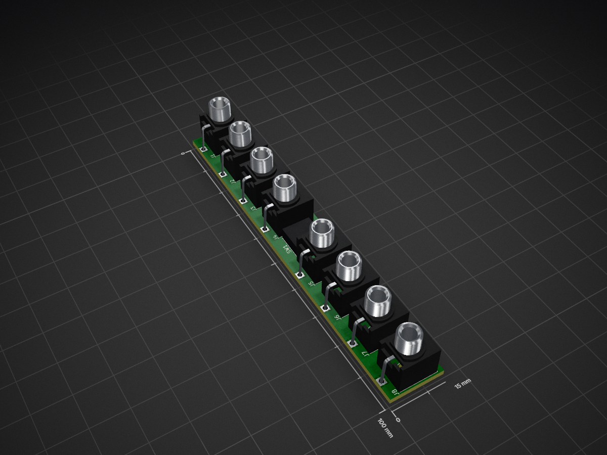
 Schenktronics/ST01-multiple
A 3HP Eurorack passive multiple from Schenktronics: two banks of four jacks, and a latching button that links them into one eight-jack multiple. The button doubles as a performance mute. No power needed.
Multiple is an open-source printed circuit board by Schenktronics, from the Schenktronics/ST01-multiple repository on GitHub. It is a 2-layer board of 15 × 100 mm with 10 parts on 13 nets, routed with 16 tracks and 0 vias.
Its parts include 8 connectors and 1 switch.

A 3HP Eurorack passive multiple from Schenktronics: two banks of four jacks, and a latching button that links them into one eight-jack multiple. The button doubles as a performance mute. No power needed.

| Document | For | |
|---|---|---|
| User Manual | Using the module | |
| Assembly Guide | Building the kit | |
| Bill of Materials (CSV) | Parts and sourcing |
hardware/
  ST01_Multiple.step          3D model of the assembled module
  multiple/                   Main PCB (KiCad 5.1 schematic, KiCad 10 PCB)
    Multiple.sch                 Schematic
    Multiple.kicad_pcb           PCB layout
    Multiple.step                3D model
    BOM.ods                      Original BOM spreadsheet
  panel/                      Faceplate (KiCad 10, made as an aluminum PCB)
    MultipleFaceplate.kicad_pcb  Faceplate layout
    MultipleFaceplate.step       3D model
  jig/                        3D-printable solder jig (see below)
    ST-01_Solder_Jig.stl         Holds the jacks and button while you solder
docs/                         Manual, assembly guide, BOM, images
  pdf/                          PDF versions of the manual and assembly guide
The .github/ folder holds the automation that builds the PDFs. You can ignore it.
| Board | Size | Layers | Thickness | Notes |
|---|---|---|---|---|
| Main PCB | 15 x 100 mm | 2 | 1.6 mm | Standard green is fine |
| Faceplate | 15 x 128.5 mm | 1 | 1.6 mm | Aluminum PCB, white solder mask, black silkscreen. Only the front copper layer is used, so FR4 works too. |
The BOM lists every part. The jack pads are oval so the board can also take panel-mount style jacks, which may be easier to source. The CUI MJ-3507 is one example: its sleeve is a solder lug rather than a pin, so each one needs a short wire from that lug to the jack's square pad.
hardware/jig/ST-01_Solder_Jig.stl is a 3D-printable jig (28 x 112 x 12 mm) that holds the eight jacks and the button square and centered while you solder them. It replaces the faceplate as the alignment guide, so all nine parts can be soldered in one go.
The pockets are a close fit (0.1 mm per side). If your printer makes holes small and the jack threads won't drop in, try a slightly larger horizontal-expansion or hole-compensation setting in your slicer.
This hardware design and its documentation are licensed under CC BY-NC-SA 4.0. See LICENSE.
The Schenktronics name and logo are trademarks of Schenktronics LLC and are not covered by the CC BY-NC-SA 4.0 license.
| Qty | Value | Footprint | References |
|---|---|---|---|
| 8 | AudioJack2_SwitchT | _NTSFootprints:Jack_3.5mm_QingPu_WQP-PJ398SM_Vertical_CenterHole_OvalPads | J1, J2, J3, J4, J5, J6, J7, J8 |
| 1 | LOGO | _NTSFootprints:SchentronicsLogoSmed | G*** |
| 1 | SW_Push_DPDT | _NTSFootprints:MHPS2285 | SW1 |
It measures 15 × 100 mm and has 2 copper layers, 1.6 mm thick.
10 parts. The full list of its parts is on this page, with links to each part's symbol and footprint where PCBKit's library has them.
From the Schenktronics/ST01-multiple repository on GitHub, at the commit this page was made from: the board is hardware/multiple/Multiple.kicad_pcb. PCBKit opens the board in the browser, with nothing to install.
Its repository states no licence, so its author keeps all rights: ask Schenktronics before reusing the design.
gusmanb/logicanalyzer
24 channel, 100Msps logic analyzer hardware and software

byrantech/laptop
anyon_e, a highly integrated, high end, open source laptop. Attempt the impossible.

joeycastillo/Sensor-Watch
A board replacement for the classic Casio F-91W wristwatch


OLIMEX/OLINUXINO
OLINUXINO is Open Source / Open Hardware, low cost from EUR 24 Linux Industrial grade Single Board Computer capable to operate -25+85C

rusefi/rusefi
rusefi - GPL internal combustion engine control unit

VoronDesign/Voron-Hardware
Cool Hardware designed by the Voron Design group

hoglet67/RGBtoHDMI
Bare-metal Raspberry Pi project that provides pixel-perfect sampling of Retro Computer RGB/YUV video and conversion to HDMI