Skip to the content
PCBKitNew board
2 layers52 × 9 mmSensorunit, the printed circuit board in 3D

The sensor unit was designed in KiCad 10 and manufactured by JLCPCB. It is built in a flex PCB material to achieve a very small build height, in order to come very close to the device under test.

Size
52 × 9 mm
Copper layers
2
Thickness
0.11 mm
Parts
3
Nets
7
Pads
20
Tracks, vias
117, 31
Pours
68
Routed
Yes
KiCad
KiCad 10.0 (file 20260206)
Created
26 Aug 2026
Updated
28 Aug 2026

Overview

Sensorunit is an open-source printed circuit board by scalinq-lab, from the scalinq-lab/cryomagsens repository on GitHub, published under the CERN-OHL-P-2.0 licence. It is a 2-layer board of 52 × 9 mm with 3 parts on 7 nets, routed with 117 tracks and 31 vias.

Its parts include 1 diode and 1 connector.

README

sensor_unit_pcb/readme.md

Sensor unit: Schematics and PCB Design
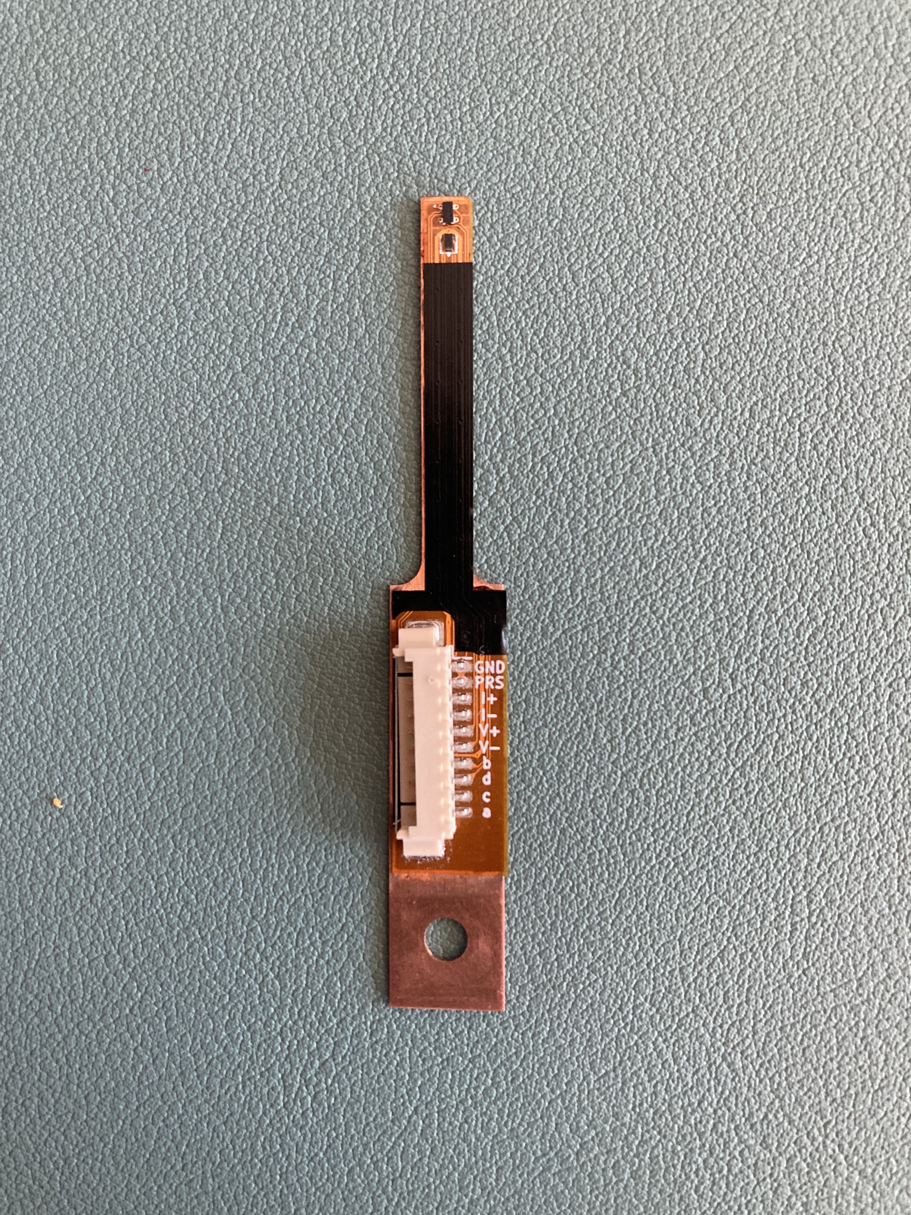
Sensor unit (Sensor unit)

Design

The sensor unit was designed in KiCad 10 and manufactured by JLCPCB. It is built in a flex PCB material to achieve a very small build height, in order to come very close to the device under test. The Flex PCB is mounted to a copper spine (see ..\mechanical_designs for the full design) for thermalisation purposes. The total build height of the sensor unit is 1.1 mm.

The sensor unit features a AKM HQ0811 InAs Hall element as a magnetic field sensor, a 1N4148 Si diode as a temperature sensor and a 10-pin Molex PicoBlade connector for a good and stable connection.

Working principle

Hall sensor

The Hall element has four nodes, here denoted a, b, c, d. When a current is pushed fron a to c, a potential difference can be measured between b and d, which scales linearly with the applied orthogonal magnetic flux density. When a current is pushed from b to d, a similar potential difference can be measured between a and c. By modulating the current directiion and through which axis the current is pushed, the remaining DC offset due to asymmetries in the element can be eliminated.

Diode temperature sensor

The sensor unit also features a 4-wire measurement setup for the diode, which acts as a temperature sensor. The nominal drive current of the diode is 10 µA.

Presence pin.

The sensor unit features a presence pin (denoted PRS), which is internally connected to the ground pin on the sensor PCB. When connected to the signal processing unit, a GPIO pin is pulled low through the sensor unit, indicating that a sensor is connected and allowing current output.

Parts

3
QtyValueFootprintReferences
110x Molex PicobladeConnector_Molex:Molex_PicoBlade_53261-1071_1x10-1MP_P1.25mm_HorizontalJ1
11N4148Diode_SMD:D_SOD-882D1
1HQ-0811SamacSys_Parts:HQ0811H1

Questions

How big is the Sensorunit PCB?

It measures 52 × 9 mm and has 2 copper layers, 0.11 mm thick.

What parts does the Sensorunit use?

3 parts. The full list of its parts is on this page, with links to each part's symbol and footprint where PCBKit's library has them.

Where can I download the Sensorunit KiCad files?

From the scalinq-lab/cryomagsens repository on GitHub, at the commit this page was made from: the board is sensor_unit_pcb/Sensorunit.kicad_pcb and its schematic sensor_unit_pcb/Sensorunit.kicad_sch. PCBKit opens the board in the browser, with nothing to install.

Can I use the Sensorunit design in my own project?

Its repository publishes it under the CERN-OHL-P-2.0 licence: you may reuse it on that licence's terms (keep the author's notice, and for a copyleft licence share your changes alike).

More from scalinq-lab/cryomagsens

1
  • 6 layers100.7 × 106.4 mmSignal processing unit, the printed circuit board in 3D

    Signal processing unit

    scalinq-lab/cryomagsens

    The sensor unit was designed in KiCad 10 and manufactured by JLCPCB. It is built in a flex PCB material to achieve a very small build height, in order to come very close to the device under test.

    178 parts2CERN-OHL-P-2.0

Similar boards

  • 2 layers40 × 30 mmBlinky, the printed circuit board in 3D

    Blinky

    earthtojake/text-to-cad

    Design physical products with AI

    3 parts26kMIT
  • 2 layers51.9 × 16 mmPassive2-rpi non standard adapter, the printed circuit board in 3D

    Passive2-rpi non standard adapter

    hzeller/rpi-rgb-led-matrix

    Controlling up to three chains of 64x64, 32x32, 16x32 or similar RGB LED displays using Raspberry Pi GPIO

    3 parts4.4kGPL-2.0
  • 2 layers16.3 × 16.3 mmSensor, the printed circuit board in 3D

    Sensor

    scottbez1/splitflap

    DIY split-flap display

    3 parts4.2k
  • 2 layersSub, the printed circuit board in 3D

    Sub

    atopile/atopile

    Design circuit boards with code! ✨ Get software-like design reuse 🚀, validation, version control and collaboration in hardware; starting with electronics ⚡️

    3 parts4kMIT
  • 2 layers85 × 30 mmDual stomp, the printed circuit board in 3D

    Dual stomp

    torvalds/GuitarPedal

    Linus learns analog circuits

    3 parts2.5kGPL-2.0
  • 2 layers124.5 × 33.7 mm172319-1 connector, the printed circuit board in 3D

    172319-1 connector

    rusefi/rusefi

    rusefi - GPL internal combustion engine control unit

    3 parts1.2k
  • 2 layers10.5 × 83 mmProgrammingAdapter, the printed circuit board in 3D

    ProgrammingAdapter

    stuartpittaway/diyBMSv4

    Version 4 of the diyBMS

    3 parts1.1k
  • 2 layers21.2 × 51.3 mmPico reset, the printed circuit board in 3D

    Pico reset

    hackclub/sprig

    🍃 Learn to code by making games in a JavaScript web-based game editor.

    3 parts1.1kMIT