
2 layers192.2 × 150.5 mm

 sbarabe/SBK_RP1
Open-source reverse polarity protection module for learning and embedded electronics projects.
SBK RP1 is an open-source printed circuit board by sbarabe, from the sbarabe/SBK_RP1 repository on GitHub, published under the CERN-OHL-P-2.0 licence. It is a 2-layer board of 8.2 × 9.9 mm with 5 parts on 5 nets, routed with 4 tracks and 4 vias.
It is built around the AO3401A. Its parts include 2 resistors, 1 diode, 1 transistor and 1 connector.
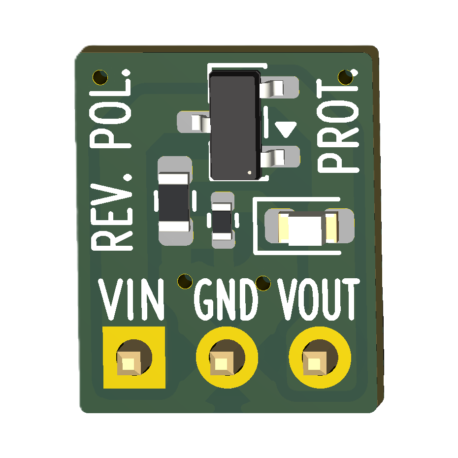
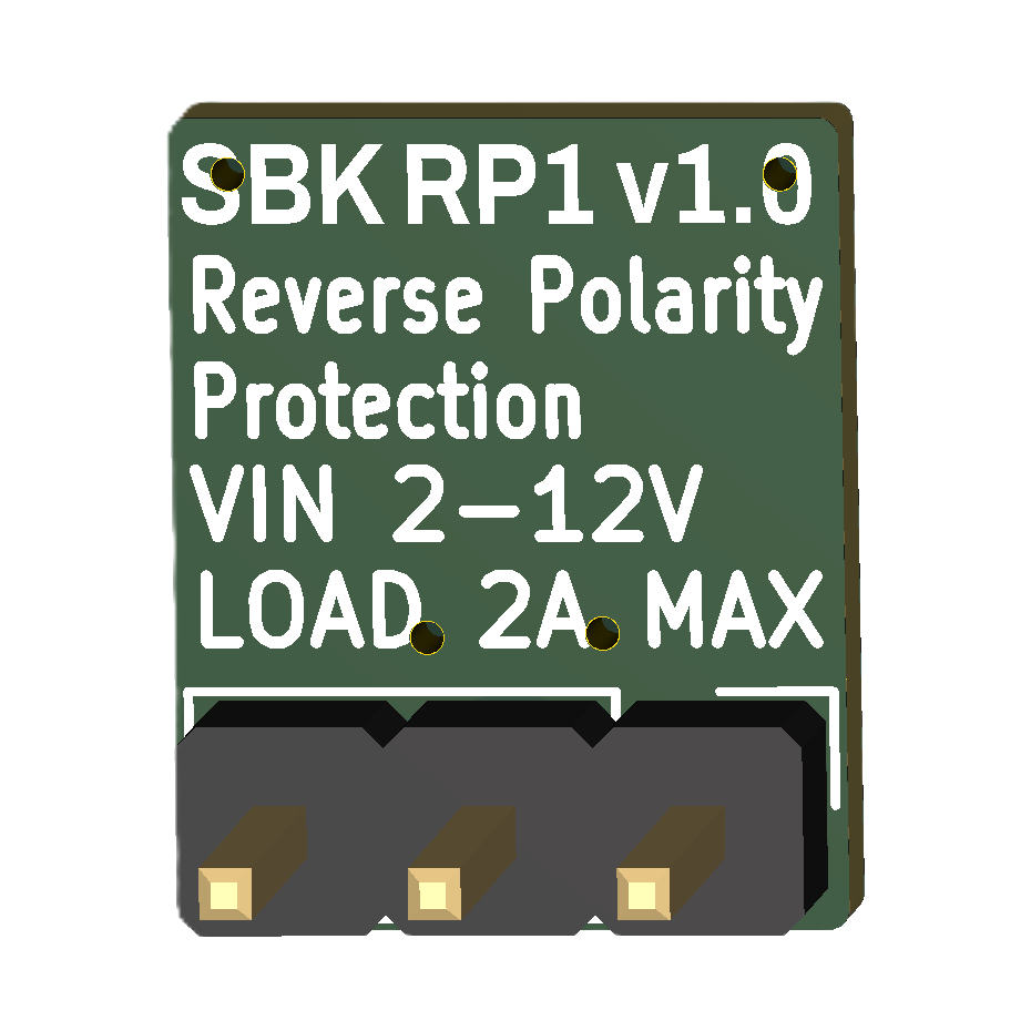
Front Back
SBK_RP1 is a compact, reusable hardware module that protects low-voltage DC electronic circuits against accidental reverse battery connections. Using a P-channel MOSFET ideal-diode topology, it provides reverse polarity protection with a much lower voltage drop than a conventional series diode. An integrated LED indicates when protected output power is available.
Designed for breadboards, prototypes, and educational projects, SBK_RP1 offers a simple way to improve the robustness and reliability of battery-powered embedded systems.
| Pin | Description |
|---|---|
| VIN | Power input (2–12 VDC) |
| GND | Ground |
| VOUT | Protected power output |
Battery
   │
SBK_RP1
   │
SBK_SP1 (optional)
   │
Embedded System
SBK_RP1 is installed between the power source and the electronic circuit. During normal operation it introduces only a very small voltage drop. If the supply is accidentally connected in reverse, the module automatically blocks current, protecting the downstream electronics.
This project is fully open-source hardware. You can:
If you prefer a ready-to-use module, fully assembled SBK_SP1 boards may be available in small batches on demand.
For availability, pricing, or quantity inquiries, contact:
These modules are intended for hobbyists, educators, prototypes, and small-scale projects. Availability depends on component stock and production capacity.
Suggestions, bug reports, and improvements are welcome.
To report a problem or suggest an improvement, open an Issue. Pull Requests are also welcome for corrections, documentation improvements, and design changes that make the project easier to understand or build.
If this project is useful for learning, teaching, or prototyping, you can support its continued development.
Donations help fund prototype hardware, documentation, educational resources, and future open-source projects.
❤️ Support the project through PayPal
Thank you for supporting open-source educational hardware.
This project is released as open-source hardware under the CERN Open Hardware Licence Version 2 - Permissive (CERN-OHL-P v2).
You are free to study, modify, manufacture, and distribute this design, provided the terms of the license are respected.
See the LICENSE file for the full license text.
This project was designed using KiCad 10.
| Qty | Value | Footprint | References |
|---|---|---|---|
| 1 | 1 x 3 pin header | Connector_PinHeader_2.54mm:PinHeader_1x03_P2.54mm_Vertical | J1 |
| 1 | 100 kΩ | Resistor_SMD:R_0603_1608Metric | R1 |
| 1 | 15 kΩ | Resistor_SMD:R_0402_1005Metric | R2 |
| 1 | AO3401A | Package_TO_SOT_SMD:SOT-23 | Q1 |
| 1 | RED | LED_SMD:LED_0603_1608Metric | D1 |

polpo/picogus
Emulation of ISA sound cards and CD-ROM on Raspberry Pi Pico (GUS, SB/Adlib, MPU-401, Tandy, CMS, Panasonic CD-ROM) with USB mouse/joystick support

osy/XG_Mobile_Station
Open source eGPU dock for ROG Ally and ROG Flow

iandchasse/silkscreen-pcb
Silkscreen: open-hardware ESP32-S3 e-paper reader mainboard (KiCad 9). Formerly the de-link hub.

BlueSCSI/BlueSCSI-v2
BlueSCSI v2/Ultra - an open source, open hardware, SCSI emulator using the Pi Pico PR2040 and Pico 2 RP2350

pms67/LittleBrain-STM32F4-Sensorboard
STM32F4-based PCB interfacing with a variety of sensors.


It measures 8.2 × 9.9 mm and has 2 copper layers, 1.6 mm thick.
5 parts, built around the AO3401A. The full list of its parts is on this page, with links to each part's symbol and footprint where PCBKit's library has them.
From the sbarabe/SBK_RP1 repository on GitHub, at the commit this page was made from: the board is hardware/KiCad/SBK_RP1.kicad_pcb and its schematic hardware/KiCad/SBK_RP1.kicad_sch. PCBKit opens the board in the browser, with nothing to install.
Its repository publishes it under the CERN-OHL-P-2.0 licence: you may reuse it on that licence's terms (keep the author's notice, and for a copyleft licence share your changes alike).