2 layers68.6 × 53.3 mm

 Sanjit1/Attiny2x4x8x-Programmers
Programmers for Attinies
NanoProgrammers is an open-source printed circuit board by Sanjit1, from the Sanjit1/Attiny2x4x8x-Programmers repository on GitHub, published under the MIT licence. It is a 2-layer board of 41 × 75 mm with 14 parts on 40 nets, routed with 78 tracks and 0 vias.
It is built around the ATTINY84-20PU, ATTINY85V-10PU and OS102011MS2QN1. Its parts include 3 connectors, 2 ICs, 1 capacitor, 1 resistor and 1 diode. It belongs with the interfaces and adapters boards and the AVR (ATmega, ATtiny) boards of this library.


These are the KiCad Files for programmers that use Arduino as ISP to program ATTinies. There is an Arduino Uno and an Arduino Nano version. There are headers for both the '5s and the '4s.
This should be fairly simple to setup. You can read a general guide over here. All this PCB does is replace the wiring to make life easier. I will be doing this in Arduino Legacy using Damellis' core. If you want to use 2.0 or SpenceKonde's core, you can do that too. Just make sure to configure it properly.
You only need to do this once. If the programmer has already been set up you don't need to do this again.
https://raw.githubusercontent.com/damellis/attiny/ide-1.6.x-boards-manager/package_damellis_attiny_index.json to the list.ATTinyCore and install it.Tools: Board, Processor, Clock, Port and Programmer.Arduino as ISP.Burn Bootloader.Ctrl+Shift+U to Upload Using Programmer.Keep in mind that if you want to program and arduino after this ,you will need to change the programmer back to AVRISP mkII or whatever you were using.
I have provided a sample blink sketch. If you find that the LED is blinking faster/slower than expected, you may need to change the clock speed. This is done by burning the bootloader again.
Arduino as ISP.avrdude: stk500_getsync() attempt 10 of 10: not in sync: resp=0x00, this is usually a wiring issue or incorrect programmer selected.avrdude: Yikes! Invalid device signature., this is usually a wiring issue or incorrect ATTiny selected.Yea, there is an LED connected to MISO. With that, you can have a startup script that helps you verify that your program successfully uploaded.
On an Attiny85: MISO is Pin 6(PB1)
On an Attiny84: MISO is Pin 8(PB5)
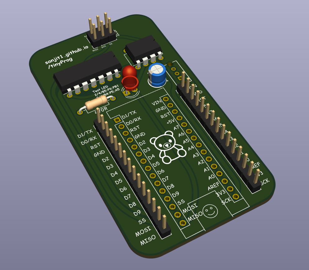
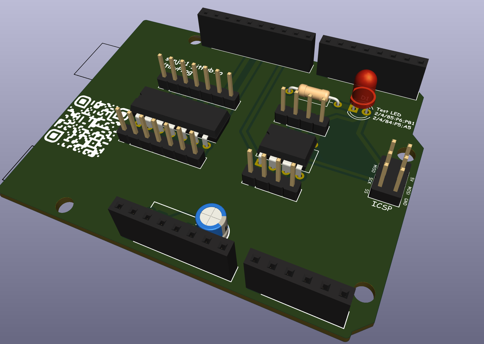
I will take an IRL pic later.
| Qty | Value | Footprint | References |
|---|---|---|---|
| 3 | LOGO | Custom Art Exports:Smiley Face | G1, G2, G3 |
| 2 | Conn_01x15_Pin | Connector_PinHeader_2.54mm:PinHeader_1x15_P2.54mm_Vertical | J1, J2 |
| 1 | 10u | Capacitor_THT:CP_Radial_D5.0mm_P2.50mm | C1 |
| 1 | 470R | Resistor_THT:R_Axial_DIN0207_L6.3mm_D2.5mm_P10.16mm_Horizontal | R1 |
| 1 | ATtiny84-20P | Package_DIP:DIP-14_W7.62mm | U1 |
| 1 | ATtiny85V-10P | Package_DIP:DIP-8_W7.62mm | U2 |
| 1 | Arduino_Nano_v3.x | Module:Arduino_Nano | A1 |
| 1 | ICSP | Connector_PinHeader_2.54mm:PinHeader_2x03_P2.54mm_Vertical | J3 |
| 1 | LED | LED_THT:LED_D4.0mm | D1 |
| 1 | LOGO | footprints:GithubQR_14 | G*** |
| 1 | OS102011MS2QN1 | OS102011MS2QN1:SPDT_OS102011_CNK | SW1 |
It measures 41 × 75 mm and has 2 copper layers, 1.6 mm thick.
14 parts, built around the ATTINY84-20PU, ATTINY85V-10PU and OS102011MS2QN1. The full list of its parts is on this page, with links to each part's symbol and footprint where PCBKit's library has them.
From the Sanjit1/Attiny2x4x8x-Programmers repository on GitHub, at the commit this page was made from: the board is NanoProgrammers/NanoProgrammers.kicad_pcb and its schematic NanoProgrammers/NanoProgrammers.kicad_sch. PCBKit opens the board in the browser, with nothing to install.
Its repository publishes it under the MIT licence: you may reuse it on that licence's terms (keep the author's notice, and for a copyleft licence share your changes alike).


HuntieDK/BMW-i3-two-phase-charging
Extends the BMW i3 60Ah BEV/REX charging to use two phases

mat3ck/eirbot1a_2018
Eirbot first year team project for 2018 France Championship of Robotics

Electro707/2019_Menorah_PCB_Kit
A soldering kit in the shape of menorah powered by an ATtiny84


