

2 layers74.4 × 51.2 mm
Esp32-wroom timer
AlessandroAU/Chorus32-ESP32LapTimer
This is an ESP32 port of the popular Chorus RF Laptimer
66 parts102GPL-3.0
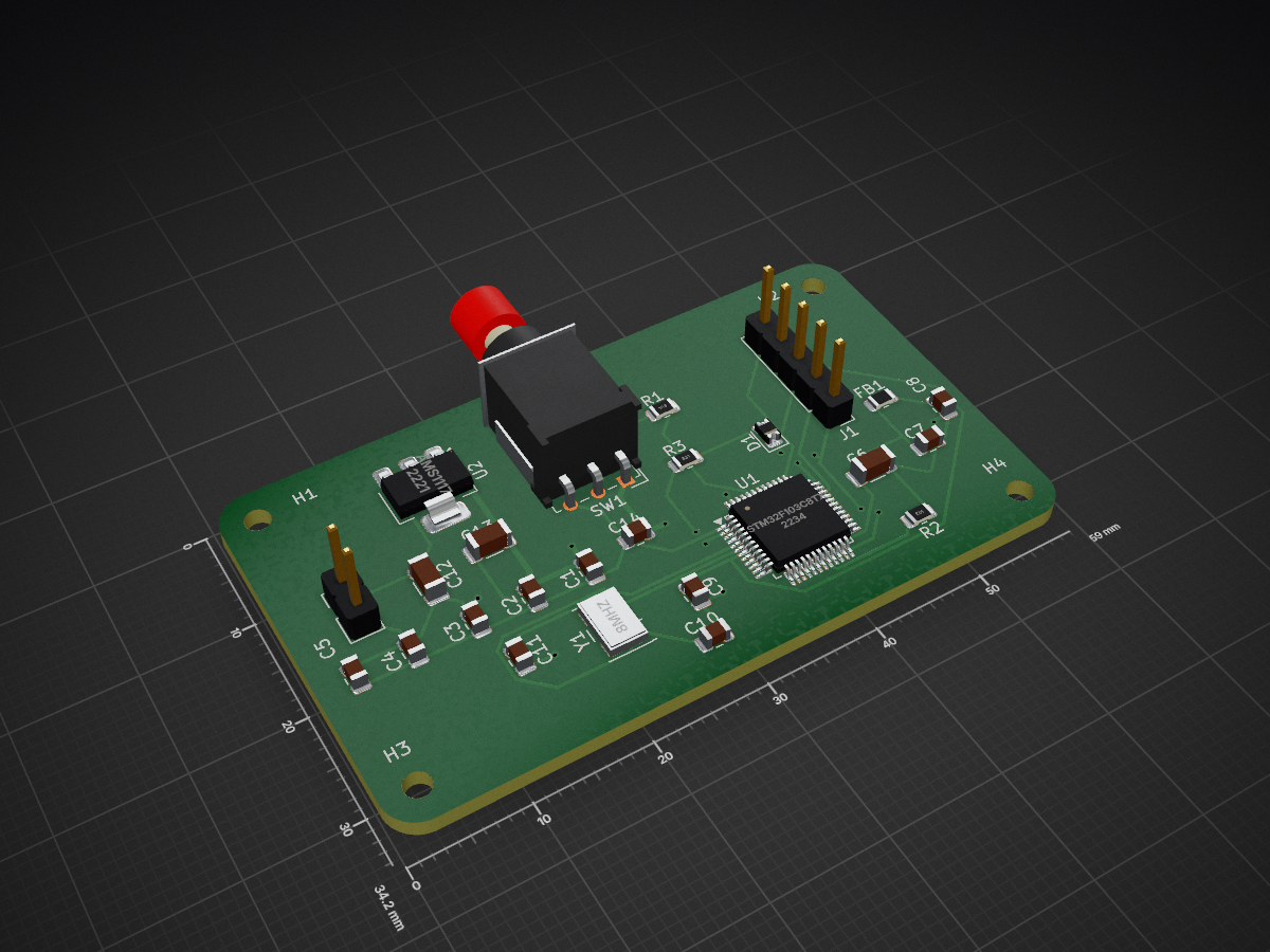
STM32 is an open-source printed circuit board by sandhya-na, from the sandhya-na/STM32_PCB_Project repository on GitHub. It is a 2-layer board of 59 × 34.2 mm with 29 parts on 45 nets, routed with 149 tracks and 16 vias.
It is built around the AMS1117. Its parts include 14 capacitors, 3 resistors, 2 ICs, 2 connectors and 1 diode. It belongs with the STM32 boards of this library.
This project contains the complete hardware design files for a custom 2-layer development board built around the STM32F103C8T6 microcontroller. I designed this entire board in KiCad. My main goal for this project was to focus on real-world board performance—making sure the power lines are stable, the clock signal doesn't pick up electrical noise, and the ground layout is solid enough to prevent signal problems. This board is ready to be used as a reliable core module for robotics or automation setups.
For the power stage, I used an AMS1117-3.3V linear regulator to drop the incoming +5V power down to the +3.3V needed by the STM32 chip. Since these regulators can get pretty hot when running, I spent extra time planning the layout around it.
The external 8 MHz crystal acts as the heartbeat of the microcontroller. If this part of the circuit picks up noise, the whole chip can freeze or misbehave.
In high-frequency digital circuits, current needs a quick, clean path to travel back to the ground. If the ground path is long and winding, it acts like an antenna and creates a lot of electrical noise. - Solid Bottom Ground Plane: I used a continuous, unbroken copper pour on the Bottom Layer (B.Cu) to act as a massive ground shield under the whole board. - Dedicated Vias: Instead of running long ground tracks on the top layer, every ground pad drops immediately down to the bottom ground plane using its own small via. This keeps the connections incredibly short and clean.
| Qty | Value | Footprint | References |
|---|---|---|---|
| 5 | 100n | Capacitor_SMD:C_0805_2012Metric | C1, C2, C3, C4, C9 |
| 4 | ~ | MountingHole:MountingHole_2.2mm_M2 | H1, H2, H3, H4 |
| 2 | 10K | Resistor_SMD:R_0805_2012Metric | R1, R2 |
| 2 | 10uF | Capacitor_SMD:C_1206_3216Metric | C12, C13 |
| 2 | 1u | Capacitor_SMD:C_0805_2012Metric | C7, C8 |
| 2 | 22pF | Capacitor_SMD:C_0805_2012Metric | C10, C11 |
| 1 | 10u | Capacitor_SMD:C_0805_2012Metric | C5 |
| 1 | 10u | Capacitor_SMD:C_1206_3216Metric | C6 |
| 1 | 10uF | Capacitor_SMD:C_0805_2012Metric | C14 |
| 1 | 120R | Resistor_SMD:R_0805_2012Metric | FB1 |
| 1 | 330R | Resistor_SMD:R_0805_2012Metric | R3 |
| 1 | 5V_input | Connector_PinHeader_2.54mm:PinHeader_1x02_P2.54mm_Vertical | J2 |
| 1 | 8MHz | Crystal:Crystal_SMD_5032-4Pin_5.0x3.2mm | Y1 |
| 1 | AMS1117 | Package_TO_SOT_SMD:SOT-223-3_TabPin2 | U2 |
| 1 | Conn_01x05 | Connector_PinHeader_2.54mm:PinHeader_1x05_P2.54mm_Vertical | J1 |
| 1 | LED | Diode_SMD:D_0805_2012Metric | D1 |
| 1 | STM32F103C8Tx | Package_QFP:LQFP-48_7x7mm_P0.5mm | U1 |
| 1 | SW_SPDT | Button_Switch_THT:SW_Lever_1P2T_NKK_GW12LxH | SW1 |
AlessandroAU/Chorus32-ESP32LapTimer
This is an ESP32 port of the popular Chorus RF Laptimer


uli/basicengine-pcb
Schematics and PCB layout for the BASIC Engine home computer


MR-DOS/TDR_diploma_thesis
Time domain reflectometer. Includes Hardware, firmware and GUI in Octave. Also a diploma thesis.
It measures 59 × 34.2 mm and has 2 copper layers, 1.6 mm thick.
29 parts, built around the AMS1117. The full list of its parts is on this page, with links to each part's symbol and footprint where PCBKit's library has them.
From the sandhya-na/STM32_PCB_Project repository on GitHub, at the commit this page was made from: the board is STM32.kicad_pcb and its schematic STM32.kicad_sch. PCBKit opens the board in the browser, with nothing to install.
Its repository states no licence, so its author keeps all rights: ask sandhya-na before reusing the design.