2 layers34 × 99.9 mm
 sandeepzgk/ESR-System
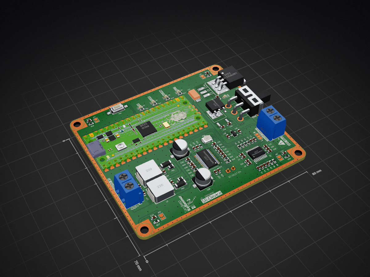
Notable parts - DAC: PCM5100A - Amplifier: TPA3112D1 - Regulators: LM78M05C, LM7812S, LM1085IS-12, AP7333-33 - Inductors/caps/resistors; Pico headers/footprints; custom logos
Sr device is an open-source printed circuit board by sandeepzgk, from the sandeepzgk/ESR-System repository on GitHub, published under the MIT licence. It is a 2-layer board of 80 × 70 mm with 97 parts on 106 nets, routed with 495 tracks and 305 vias.
It is built around the TPA3112D1PWPR, LM78M05CDTX/NOPB and PTS636SK25SMTRLFS, with the SS-12D11L7 among its other parts. Its parts include 42 capacitors, 21 resistors, 6 ICs, 5 diodes and 3 connectors. It belongs with the RP2040 boards of this library.


KiCad project for the ESR hardware: a Pico‑based audio playback/amp board ("sr-device"). Includes:
Notable parts
Open in KiCad 7/8
Generate fabrication
JLC integration workflow
Design choices
| Qty | Value | Footprint | References |
|---|---|---|---|
| 11 | 100nF | Capacitor_SMD:C_0603_1608Metric | C5, C8, C9, C11, C14, C15, C16, C17, C19, C24, C27 |
| 9 | 1uF | Capacitor_SMD:C_0603_1608Metric | C6, C13, C20, C21, C29, C30, C31, C32, C33 |
| 8 | 10K | Resistor_SMD:R_0603_1608Metric | R4, R7, R15, R16, R17, R18, R19, R20 |
| 6 | 1nF | Capacitor_SMD:C_0603_1608Metric | C23, C26, C34, C36, C40, C41 |
| 5 | 1K | Resistor_SMD:R_0603_1608Metric | R11, R12, R13, R14, R21 |
| 5 | LED_Small | LED_SMD:LED_0603_1608Metric | D1, D2, D3, D4, D5 |
| 4 | 10uF | Capacitor_SMD:C_0603_1608Metric | C7, C10, C12, C22 |
| 4 | MountingHole | MountingHole:MountingHole_3.2mm_M3_ISO7380_Pad | H1, H2, H3, H4 |
| 4 | SolderJumper_2_Open | Jumper:SolderJumper-2_P1.3mm_Open_TrianglePad1.0x1.5mm | JP1, JP2, JP3, JP4 |
| 3 | 10R | Resistor_SMD:R_0603_1608Metric | R22, R23, R24 |
| 3 | 56R | Resistor_SMD:R_0603_1608Metric | R1, R2, R3 |
| 2 | 0.47uF | Capacitor_SMD:C_0603_1608Metric | C38, C39 |
| 2 | 0.68uF | Capacitor_SMD:C_0603_1608Metric | C35, C37 |
| 2 | 100uF | Capacitor_SMD:CP_Elec_6.3x5.4 | C25, C28 |
| 2 | 2.2nF | Capacitor_SMD:C_0603_1608Metric | C2, C3 |
| 2 | 2.2uF | Capacitor_SMD:C_0603_1608Metric | C1, C4 |
| 2 | 22uH | IHLP3232DZER220M11:footprint | L1, L2 |
| 2 | 470R | Resistor_SMD:R_0603_1608Metric | R5, R6 |
| 2 | 75Ω | Inductor_SMD:L_1806_4516Metric | FB2, FB4 |
| 2 | 80Ω | Inductor_SMD:L_0805_2012Metric | FB1, FB3 |
| 2 | KF301-5_0-2P | KF301-5_0-2P:footprint | J1, J2 |
| 1 | 0.22uF | Capacitor_SMD:C_0603_1608Metric | C18 |
| 1 | 10K | VG039NSNXTB103:footprint | RV1 |
| 1 | 68uF | TAJC686K016RNJ:footprint | C43 |
| 1 | AP7333-33SRG-7 | AP7333-33SRG-7:footprint | U9 |
| 1 | Conn_01x02_Pin | Connector_PinHeader_2.54mm:PinHeader_1x02_P2.54mm_Vertical | J3 |
| 1 | LM7812S-TR | LM7812S-TR:footprint | U2 |
| 1 | LM78M05CDTX/NOPB | LM78M05CDTX-NOPB:footprint | U8 |
| 1 | LOGO | Icons:fa-triangle-exclamation | G*** |
| 1 | LOGO | Harvi:harvi_05 | G*** |
| 1 | PCM5100APWR | Package_SO:TSSOP-20_4.4x6.5mm_P0.65mm | U3 |
| 1 | PTS636SK25SMTRLFS | PTS636SK25SMTRLFS:footprint | SW1 |
| 1 | Pico | MCU_RaspberryPi_and_Boards:RPi_Pico_SMD_TH | U1 |
| 1 | SS-12D11L7 | SS-12D11L7:SS-12D11L7 | SW2 |
| 1 | SolderJumper_3_Bridged12 | Jumper:SolderJumper-3_P1.3mm_Bridged12_RoundedPad1.0x1.5mm | JP5 |
| 1 | TPA3112D1PWPR | TPA3112D1PWPR:footprint | U11 |

danielwilczak101/EasyControls
Originally part of the NASA Asteroid flyer program has been repurposed by the EPPL to allow anyone interested in controls to go online and connect with a real working device and test their own control algorithms on a…

griffotron/MotionModuleSTM32R8
PCB design and code for the STM32 powered Motion Module that controls 14 stepper motors


blark/6809sidecar
Experimental daughter board for the Tang Primer 20k Lite

lightningspore/shieldsigner-dev
ShieldSigner Luckfox carrier: KiCad design, smartcard docs, reproducible build tools and HTMX knowledge site

robertxdx/ESP32S3PD15W
A 15 W USB-C powered ESP32-S3 LED-strip controller and development board.

It measures 80 × 70 mm and has 2 copper layers, 1.6 mm thick.
97 parts, built around the TPA3112D1PWPR, LM78M05CDTX/NOPB, PTS636SK25SMTRLFS and SS-12D11L7. The full list of its parts is on this page, with links to each part's symbol and footprint where PCBKit's library has them.
From the sandeepzgk/ESR-System repository on GitHub, at the commit this page was made from: the board is PCB/sr-device.kicad_pcb and its schematic PCB/sr-device.kicad_sch. PCBKit opens the board in the browser, with nothing to install.
Its repository publishes it under the MIT licence: you may reuse it on that licence's terms (keep the author's notice, and for a copyleft licence share your changes alike).