4 layers100 × 68 mm
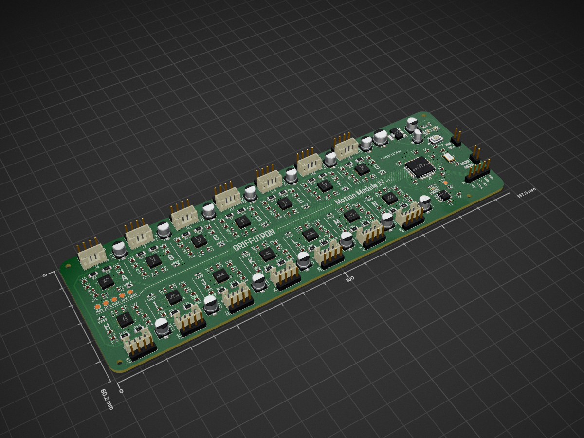
 griffotron/MotionModuleSTM32R813
PCB design and code for the STM32 powered Motion Module that controls 14 stepper motors
MotionModuleSTM32F103R8 is an open-source printed circuit board by griffotron, from the griffotron/MotionModuleSTM32R8 repository on GitHub, published under the MIT licence. It is a 4-layer board of 187.9 × 60.2 mm with 246 parts on 313 nets, routed with 2,348 tracks and 309 vias.
It is built around the STM32F103R8T6, TMC2209-LA-T and AMS1117-3.3, with the CC0603KRX7R9BB104, PT1206FR-7W0R2L and RST47UF25V035 among its other parts. Its parts include 141 capacitors, 46 resistors, 31 connectors, 17 ICs and 3 diodes. It belongs with the robots and motor control boards and the STM32 boards of this library.


This repository contains the PCB design files and source code for the STM32 based Motion Module used in my Mechanical Display.
The Motion Module uses an STM32F103R8 microcontroller to run 14 Trinamic TMC2209 stepper drivers. It recieves motor movement commands via CAN Bus from the ESP32 based Motion Controller. Please see the related repos for the ESP32 Controller and CAD Designs.
Click below to watch the full build video on YouTube

You'll need at least KiCad 8 to view and modify the PCB design files. The PCB/production folder contains files suitable for production with JLC PCB, including a zip containing the Gerbers for fabrication and bom.csv and positions.csv for SMT assembly. The bom.csv uses components from LCSC.com. If any components are no longer be available/out of stock you'll need to select an alternative.
The code uses PlatformIO (I used the VSCode plugin) and the Arduino framework.
CAN Bus library is from https://github.com/pazi88/CANBus
| Qty | Value | Footprint | References |
|---|---|---|---|
| 65 | 0.1u 50V | Capacitor_SMD:C_0603_1608Metric | C1, C10, C11, C12, C101, C103, C106, C107, C109, C111, C114, C115, C117, C119, C122, C123 +49 |
| 28 | 0R11 | Resistor_SMD:R_1206_3216Metric | R10, R11, R12, R13, R14, R15, R16, R17, R18, R19, R20, R21, R22, R23, R24, R25 +12 |
| 28 | 10u 35V | Capacitor_SMD:C_0603_1608Metric | C16, C17, C24, C25, C32, C33, C40, C41, C48, C49, C104, C105, C112, C113, C120, C121 +12 |
| 15 | 4.7u 10v | Capacitor_SMD:C_0603_1608Metric | C6, C22, C30, C38, C46, C54, C62, C70, C78, C86, C94, C102, C110, C118, C126 |
| 15 | 47u | Capacitor_SMD:CP_Elec_5x5.4 | C2, C128, C129, C130, C131, C132, C133, C134, C135, C136, C137, C138, C139, C140, C141 |
| 14 | 22n 50V | Capacitor_SMD:C_0603_1608Metric | C20, C28, C36, C44, C52, C60, C68, C76, C84, C92, C100, C108, C116, C124 |
| 14 | Conn_01x04_Pin | Connector_JST:JST_PH_B4B-PH-K_1x04_P2.00mm_Vertical | J3, J5, J7, J9, J11, J13, J15, J17, J19, J21, J26, J28, J30, J32 |
| 14 | Conn_01x04_Pin | Connector_PinHeader_2.54mm:PinHeader_1x04_P2.54mm_Vertical | J4, J6, J8, J10, J12, J14, J16, J18, J20, J23, J24, J25, J27, J29 |
| 14 | R | Resistor_SMD:R_0603_1608Metric_Pad0.98x0.95mm_HandSolder | R33, R34, R35, R36, R37, R38, R39, R40, R41, R42, R43, R44, R45, R46 |
| 14 | TMC2209 | TMC2209:QFN28_5X5_TRI | U4, U5, U6, U7, U8, U9, U10, U11, U12, U13, U14, U15, U16, U17 |
| 2 | 30pf | Capacitor_SMD:C_0603_1608Metric | C14, C15 |
| 2 | 500 | Resistor_SMD:R_0603_1608Metric | R2, R4 |
| 2 | Screw_Terminal_01x02 | Connector_PinHeader_2.54mm:PinHeader_1x02_P2.54mm_Vertical | J1, J22 |
| 1 | 100u | Capacitor_SMD:CP_Elec_6.3x4.9 | C3 |
| 1 | 10k | Resistor_SMD:R_0603_1608Metric | R3 |
| 1 | 10u | Capacitor_SMD:CP_Elec_4x5.7 | C4 |
| 1 | 12v PWR LED | LED_SMD:LED_0603_1608Metric | D1 |
| 1 | 2k | Resistor_SMD:R_0603_1608Metric | R1 |
| 1 | 3.3v PWR LED | LED_SMD:LED_0603_1608Metric | D2 |
| 1 | AMS1117-3.3 | Package_TO_SOT_SMD:SOT-223-3_TabPin2 | U1 |
| 1 | BOOT0 TP | TestPoint:TestPoint_Pad_D2.0mm | TP1 |
| 1 | Conn_01x05_Pin | Connector_PinHeader_2.54mm:PinHeader_1x05_P2.54mm_Vertical | J2 |
| 1 | Crystal | Crystal:Crystal_SMD_5032-2Pin_5.0x3.2mm | Y1 |
| 1 | DIAG | TestPoint:TestPoint_Pad_D2.0mm | TP30 |
| 1 | INDEX | TestPoint:TestPoint_Pad_D2.0mm | TP58 |
| 1 | MCP2562-E-SN | Package_SO:SOIC-8_3.9x4.9mm_P1.27mm | U2 |
| 1 | MS1 | TestPoint:TestPoint_Pad_D2.0mm | TP16 |
| 1 | MS2 | TestPoint:TestPoint_Pad_D2.0mm | TP2 |
| 1 | RESET | Button_Switch_SMD:SW_Tactile_SPST_NO_Straight_CK_PTS636Sx25SMTRLFS | SW1 |
| 1 | STATUS LED | LED_SMD:LED_0603_1608Metric | D3 |
| 1 | STM32F103R8Tx | Package_QFP:LQFP-64_10x10mm_P0.5mm | U3 |
| 1 | UART | TestPoint:TestPoint_Pad_D2.0mm | TP44 |

CaptainDJMax/2627_Projet3AMSC_Index_Stellaire
Ceci est notre projet sur l'index stellaire

stefanskotte/Nano-Tek
A tiny, modern reimagining of the classic Gotek floppy-disk-drive emulator. Nano-Tek keeps the full feature set of a Gotek-style FDD emulator but packs it onto a board that is a fraction of the size, hence the name…

zarlicho/Qris-soundbox-esp32
QRIS Soundbox adalah sistem notifikasi pembayaran realtime yang dikembangkan untuk menerima dan memproses notifikasi pembayaran QRIS melalui protokol MQTT.

JuanPoueriet/automatic-spork
Máquina de ruleta física de casino. 6 PCBs: pic32main (cerebro), wheel (rueda de LEDs), displaysa/b/c (paneles de 7 segmentos en cascada) y buttons (botonera).

SuzieLinux/kicad_projects
This repository has misc kicad projects If you feel that it is worth something for you you can go to my website and make a donation using the donate button which brings you to paypal https://suzielinux.com/


A1DS19/drone-flight-controller
A custom drone flight controller, designed in KiCad 10: an STM32F103R8T6 flight core paired with an ATmega328P telemetry co-processor on a four-layer, 102 × 49 mm PCB — taken from schematic capture through placement…
It measures 187.9 × 60.2 mm and has 4 copper layers, 1.6 mm thick.
246 parts, built around the STM32F103R8T6, TMC2209-LA-T, AMS1117-3.3 and CC0603KRX7R9BB104. The full list of its parts is on this page, with links to each part's symbol and footprint where PCBKit's library has them.
From the griffotron/MotionModuleSTM32R8 repository on GitHub, at the commit this page was made from: the board is PCB/MotionModuleSTM32F103R8/MotionModuleSTM32F103R8.kicad_pcb and its schematic PCB/MotionModuleSTM32F103R8/MotionModuleSTM32F103R8.kicad_sch. PCBKit opens the board in the browser, with nothing to install.
Its repository publishes it under the MIT licence: you may reuse it on that licence's terms (keep the author's notice, and for a copyleft licence share your changes alike).