


4 layers100 × 77.4 mm

 samanbeer/Samot2040_devboard
My custom devboard based on RP2040 chip
Samot2040 devboard is an open-source printed circuit board by samanbeer, from the samanbeer/Samot2040_devboard repository on GitHub. It is a 2-layer board of 21 × 51 mm with 41 parts on 62 nets, routed with 641 tracks and 36 vias.
It is built around the RP2040, MX25L6433FM2I-08G and BAT54C. Its parts include 20 capacitors, 9 resistors, 4 ICs, 3 connectors and 2 switches. It belongs with the microcontroller boards boards and the RP2040 boards of this library.


Because I wanted to design my own RP2040 board with my own design a to be able to say "I made this" with:
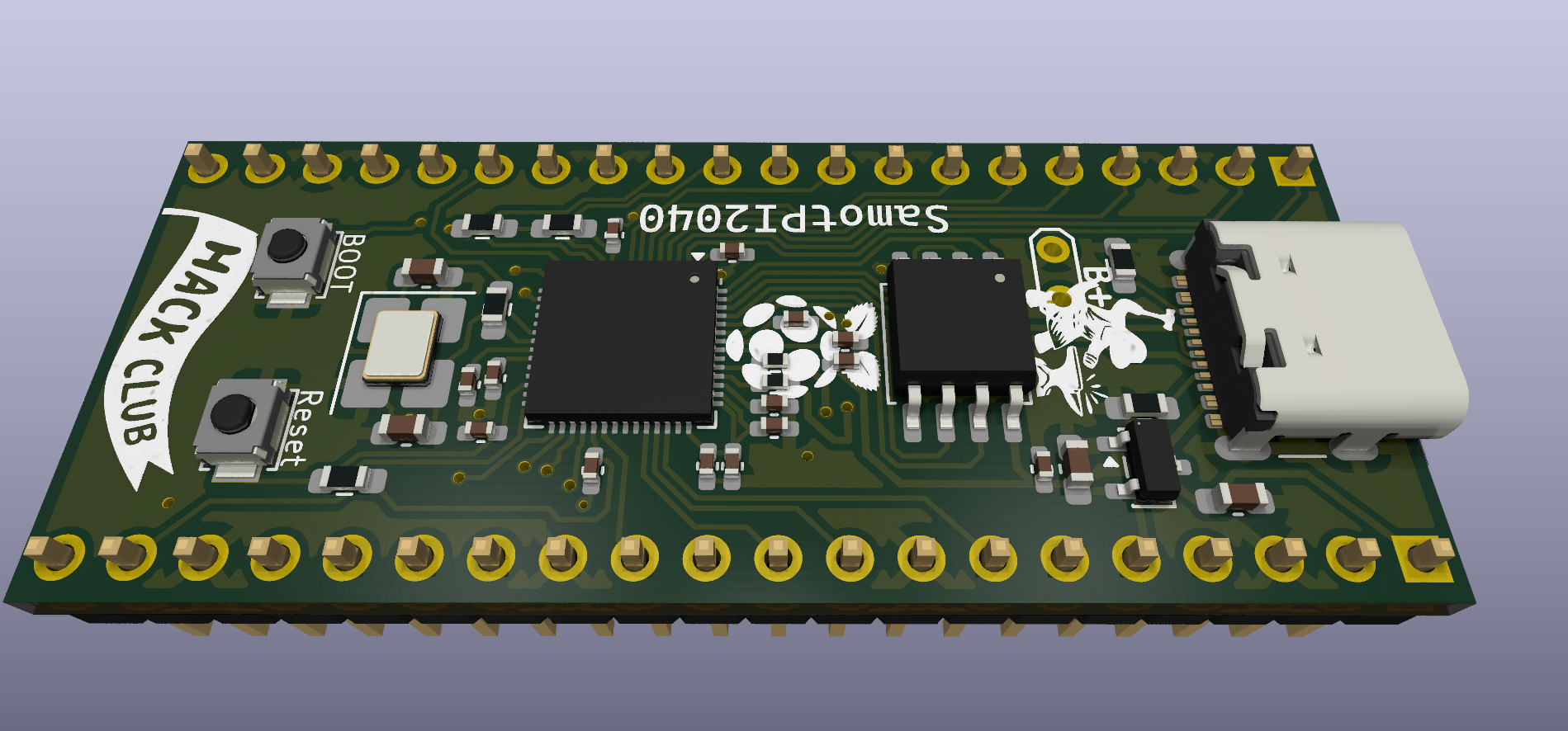
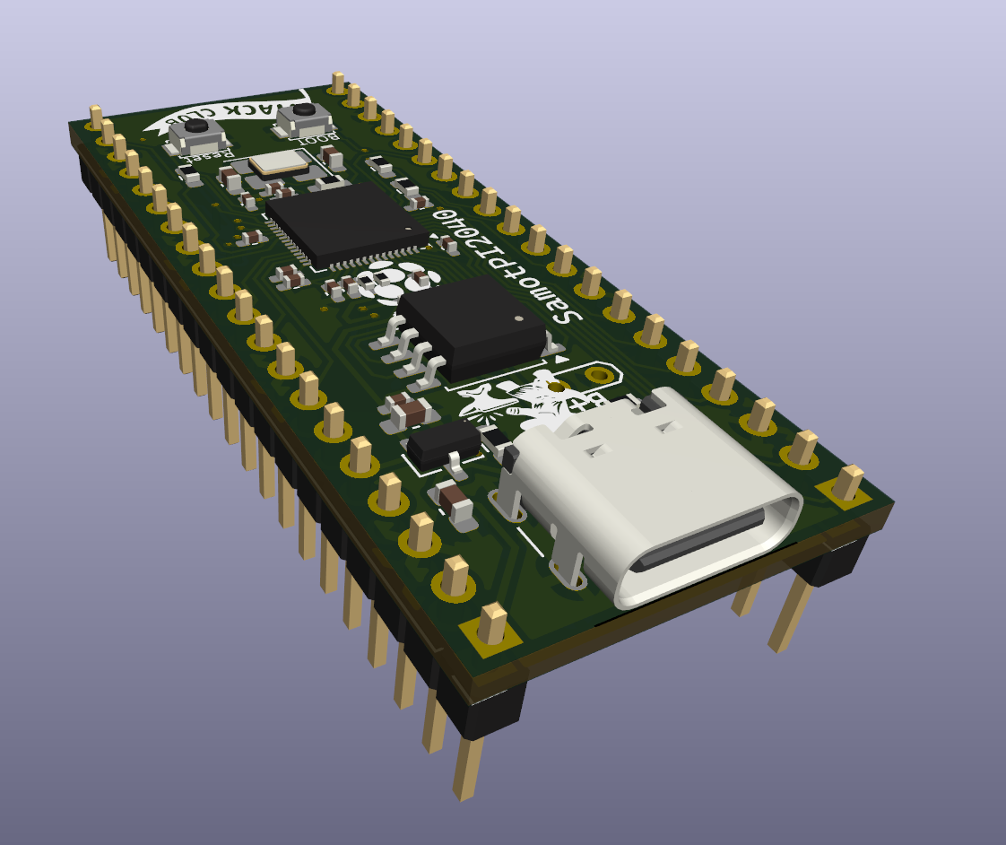
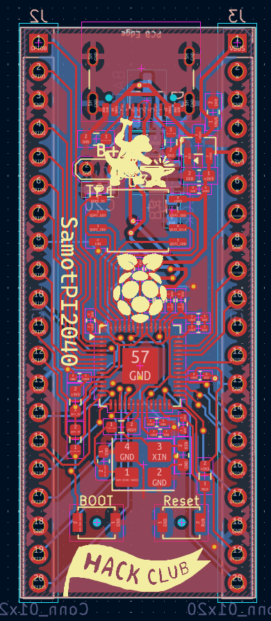
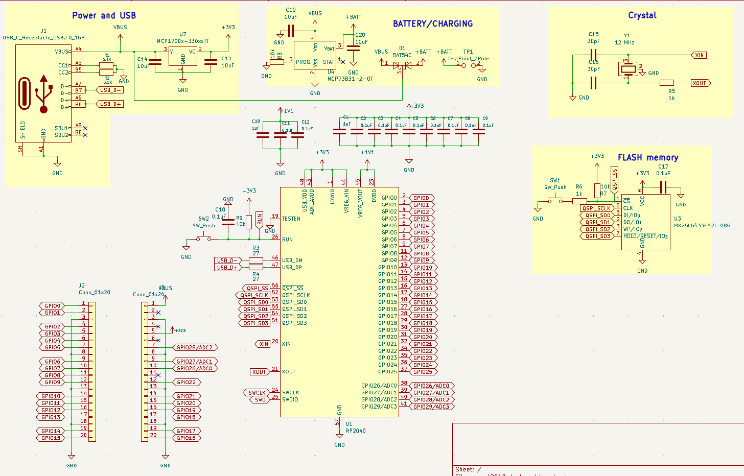
| Feature | Specification |
|---|---|
| Microcontroller | Raspberry Pi RP2040 (Dual-core ARM Cortex-M0+ up to 133 MHz, 264 KB on-chip SRAM) |
| Flash Memory | 8 MB (64 Mbit) SPI Flash (Macronix MX25L6433FM2I-08G, SOIC-8) |
| Power Input | USB-C 5V VBUS or Li-Po / Li-Ion 3.7V Battery |
| Battery Charger | Microchip MCP73831-2-OT (Single-cell Li-Po/Li-Ion linear charge manager, 4.2V CC/CV) |
| Power Multiplexing | BAT54C dual Schottky barrier diode (automatic power source switching between USB and Battery) |
| Voltage Regulation | Microchip MCP1700T-3302E/TT (3.3V Low-Dropout Regulator, 250mA output) |
| Expansion / I/O | 2x 1x20-pin 2.54mm pitch headers (breadboard compatible) |
The board features a built-in power management circuit designed for both desktop development and portable battery-powered operation:
+BATT and GND pins/pads.[!IMPORTANT] I recommend using HOT airflow station or hot plate for soldering because there are really small components like the main chip or 0402 capacitors/resistors
VBUS (5V), 3V3, and GND are not shorted.The RP2040 has a built-in ROM bootloader that makes flashing firmware simple without requiring external programmers:
flowchart LR
    A["Hold BOOT"] --> B["Plug in USB-C"]
    B --> C["'RPI-RP2' Drive Appears"]
    C --> D["Drag & Drop .UF2 File"]
D --> E["Auto Reboot & Run!"]BOOT button (SW1).BOOT button..uf2 firmware file onto the RPI-RP2 drive that should appear on PC:
.uf2 file..uf2 file finishes copying, the board will automatically dismount and execute the program immediately.Import
quickOrder_TME.csvdirectly to TME.eu for fast order.
| Qty | Value | Reference | Footprint | Where | Cost (USD) |
|---|---|---|---|---|---|
| 1 | RP2040 | U1 | QFN-56-1EP (7x7mm, 0.4mm pitch) | TME LINK | $1.02 |
| 1 | MX25L6433FM2I-08G (8MB Flash) | U3 | SOIC-8 (5.3x5.3mm, 1.27mm pitch) | TME LINK | $2.40 |
| 1 | MCP1700T-3302E/TT (3.3V LDO) | U2 | SOT-23 | TME LINK | $0.65 |
| 1 | 12 MHz Crystal | Y1 | SMD 3225-4Pin (3.2x2.5mm) | TME LINK | $0.39 |
| 1 | USB-C Receptacle 16P | J1 | GCT_USB4105 | TME LINK | $0.75 |
| 2 | Tactile Switch SPST | SW1, SW2 | SMD (Omron B3U-1000P-B) | TME LINK | $1.95 |
| 12 | 0.1 µF (100nF) 16V | C2, C3, C4, C5, C6, C7, C8, C9, C11, C12, C17, C18 | C_0402 (1005 Metric) | TME LINK | $0.17 |
| 2 | 1 µF 25V | C1, C10 | C_0402 (1005 Metric) | TME LINK | $0.095 |
| 4 | 10 µF 10V | C13, C14, C19, C20 | C_0603 (1608 Metric) | TME LINK | $0.60 |
| 2 | 27 pF 50V | C15, C16 | C_0603 (1608 Metric) | TME LINK | $0.043 |
| 2 | 27 Ω 1% | R3, R4 | R_0402 (1005 Metric) | TME LINK | $0.25 |
| 2 | 5.1 kΩ 1% | R1, R2 | R_0603 (1608 Metric) | TME LINK | $0.18 |
| 2 | 1 kΩ 1% | R5, R6 | R_0603 (1608 Metric) | TME LINK | $0.015 |
| 2 | 10 kΩ 1% | R7, R8, R9 | R_0603 (1608 Metric) | TME LINK | $0.15 |
| 2 | Pin Header 1x20 (2.54mm) | J2, J3 | PinHeader_1x20_P2.54mm_Vertical | TME LINK | $4.5(I dont need these. Already own) |
| 1 | MCP73831-2-OT | U4 | SOT-23-5_HandSoldering | TME LINK | ~$0.75 |
| 1 | BAT54C | D1 | SOT-23_Handsoldering | TME LINK | ~$0.07 |
| 1 | Li-Po 3.7V Battery | - | - | TME LINK | ~$5.7 |
| 1 | **PCB ** | PCB | 2-layer FR-4 (1.6mm, ENIG/HASL) | JLCPCB | ~$13.45 |
| - | Estimated Shipping | - | - | - | ~$8.21 |
| Total | ~$41,34 |
| Qty | Value | Footprint | References |
|---|---|---|---|
| 12 | 0.1uF | Capacitor_SMD:C_0402_1005Metric_Pad0.74x0.62mm_HandSolder | C2, C3, C4, C5, C6, C7, C8, C9, C11, C12, C17, C18 |
| 4 | 10uF | Capacitor_SMD:C_0603_1608Metric_Pad1.08x0.95mm_HandSolder | C13, C14, C19, C20 |
| 3 | 10k | Resistor_SMD:R_0603_1608Metric_Pad0.98x0.95mm_HandSolder | R7, R8, R9 |
| 2 | 1k | Resistor_SMD:R_0603_1608Metric_Pad0.98x0.95mm_HandSolder | R5, R6 |
| 2 | 1uF | Capacitor_SMD:C_0402_1005Metric_Pad0.74x0.62mm_HandSolder | C1, C10 |
| 2 | 27 | Resistor_SMD:R_0402_1005Metric_Pad0.72x0.64mm_HandSolder | R3, R4 |
| 2 | 30pF | Capacitor_SMD:C_0603_1608Metric_Pad1.08x0.95mm_HandSolder | C15, C16 |
| 2 | 5.1K | Resistor_SMD:R_0603_1608Metric_Pad0.98x0.95mm_HandSolder | R1, R2 |
| 2 | Conn_01x20 | Connector_PinHeader_2.54mm:PinHeader_1x20_P2.54mm_Vertical | J2, J3 |
| 2 | SW_Push | Button_Switch_SMD:SW_SPST_B3U-1000P-B | SW1, SW2 |
| 1 | 12 MHz | Crystal:Crystal_SMD_3225-4Pin_3.2x2.5mm_HandSoldering | Y1 |
| 1 | BAT54C | Package_TO_SOT_SMD:SOT-23_Handsoldering | D1 |
| 1 | MCP1700x-330xxTT | Package_TO_SOT_SMD:SOT-23 | U2 |
| 1 | MCP73831-2-OT | Package_TO_SOT_SMD:SOT-23-5_HandSoldering | U4 |
| 1 | MX25L6433FM2I-08G | Package_SO:SOIC-8_5.3x5.3mm_P1.27mm | U3 |
| 1 | RP2040 | Package_DFN_QFN:QFN-56-1EP_7x7mm_P0.4mm_EP3.2x3.2mm | U1 |
| 1 | TestPoint_2Pole | TestPoint:TestPoint_2Pads_Pitch2.54mm_Drill0.8mm | TP1 |
| 1 | USB_C_Receptacle_USB2.0_16P | Connector_USB:USB_C_Receptacle_GCT_USB4105-xx-A_16P_TopMnt_Horizontal | J1 |


emeb/RP2040_Audio
A Eurorack module for stereo audio effects based on the Raspberry Pi RP2040 MCU


emeb/RP2040_Projects
A collection of random projects based on the Raspberry Pi RP2040 MCU


chpaxson/Echo-Telepresence
UC Berkeley ME 135/235 Spring 2025 Term Project

It measures 21 × 51 mm and has 2 copper layers, 1.6 mm thick.
41 parts, built around the RP2040, MX25L6433FM2I-08G and BAT54C. The full list of its parts is on this page, with links to each part's symbol and footprint where PCBKit's library has them.
From the samanbeer/Samot2040_devboard repository on GitHub, at the commit this page was made from: the board is samot2040_devboard.kicad_pcb and its schematic samot2040_devboard.kicad_sch. PCBKit opens the board in the browser, with nothing to install.
Its repository states no licence, so its author keeps all rights: ask samanbeer before reusing the design.