Skip to the content
PCBKitNew board
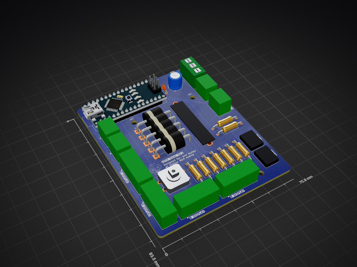
4 layers75.9 × 93.5 mmNerf timer, the printed circuit board in 3D

DIY Arduino Nano ESP32 King of the Hill timer for Nerf, foam flinging, skirmish games, and objective-based events. Includes build guide, firmware, BOM, schematic, and phone referee UI.
Size
75.9 × 93.5 mm
Copper layers
4
Thickness
1.6 mm
Parts
35
Nets
39
Pads
104
Tracks, vias
147, 0
Pours
2
Routed
Yes
KiCad
KiCad 9.0 (file 20241229)
Created
25 May 2026
Updated
7 Oct 2026

Overview

Nerf timer is an open-source printed circuit board by Salted-Peanuts, from the Salted-Peanuts/KOTH-Timer repository on GitHub, published under the MIT licence. It is a 4-layer board of 75.9 × 93.5 mm with 35 parts on 39 nets, routed with 147 tracks and 0 vias.

Its parts include 9 resistors, 7 diodes, 4 switches, 2 capacitors and 1 IC. It belongs with the radio and wireless and interfaces and adapters boards and the ESP32 and AVR (ATmega, ATtiny) boards of this library.

README

README.md

KOTH-Timer

A DIY Arduino Nano ESP32 King of the Hill timer for Nerf, foam flinging, skirmish games, and objective-based events.

KOTH-Timer is an open-source physical game timer with arcade buttons, TM1637 displays, battery monitoring, and a local phone-friendly referee/admin web interface. It is designed for two-team King of the Hill games where players physically hold a button to capture the objective.

This project is based on a working timer that has been tested successfully at local Nerf events. A few people in the hobby scene asked how to build their own, so this repo exists to make that possible.

The goal is to keep it practical, buildable, and easy to modify.

Current Recommended Versions

The current recommended firmware release is:

text
v0.3.1

v0.3.1 is the recommended firmware for new builds.

It keeps the tested v0.3 phone/referee UI and adds small UI input fixes so team colours and match duration can be edited more reliably from the web interface.

Recommended PCB revision:

text
v0.2

PCB v0.2 has been manufactured, assembled, and tested with no known faults. It is the recommended PCB revision for new builds.

The tested KOTH Timer PCB v0.2 project is available on PCBWay for convenience if you choose to use them:

Order / view the KOTH Timer PCB v0.2 project on PCBWay

Older versions remain available for reference but are not recommended for new builds:

VersionStatus
Firmware v0.3Event-tested release, replaced by v0.3.1 bug-fix update
PCB v0.1Manufactured, functional through the web UI, but has known display issues

What It Does

KOTH-Timer is a physical objective timer for two-team King of the Hill style games.

Players press their team’s button to capture the objective. The timer tracks control time and shows the game state through:

  • Large physical displays
  • Button LED feedback
  • A local referee/admin web interface

The timer runs locally from the ESP32, so it does not need internet access during gameplay.

Prototype Photos

Finished Prototype

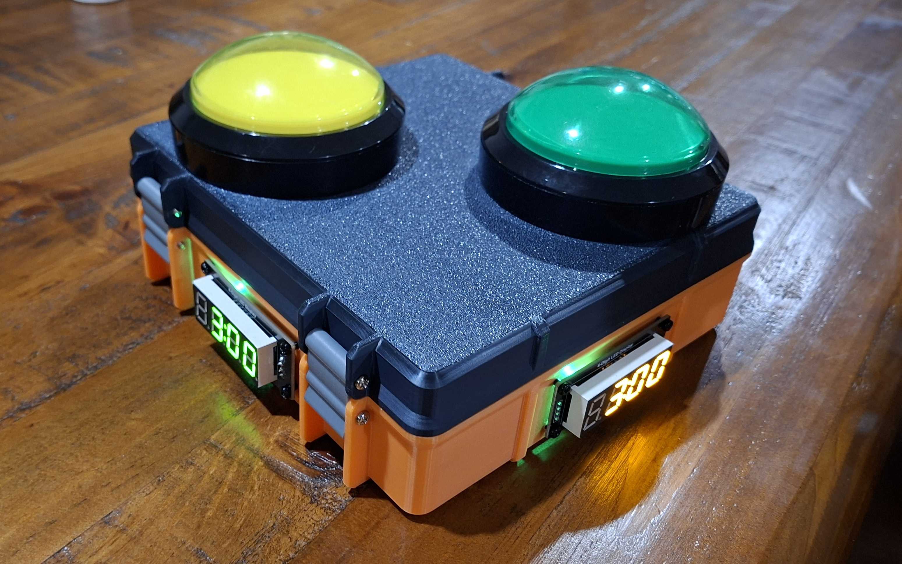
KOTH-Timer Timer finished prototype

Inside Wiring

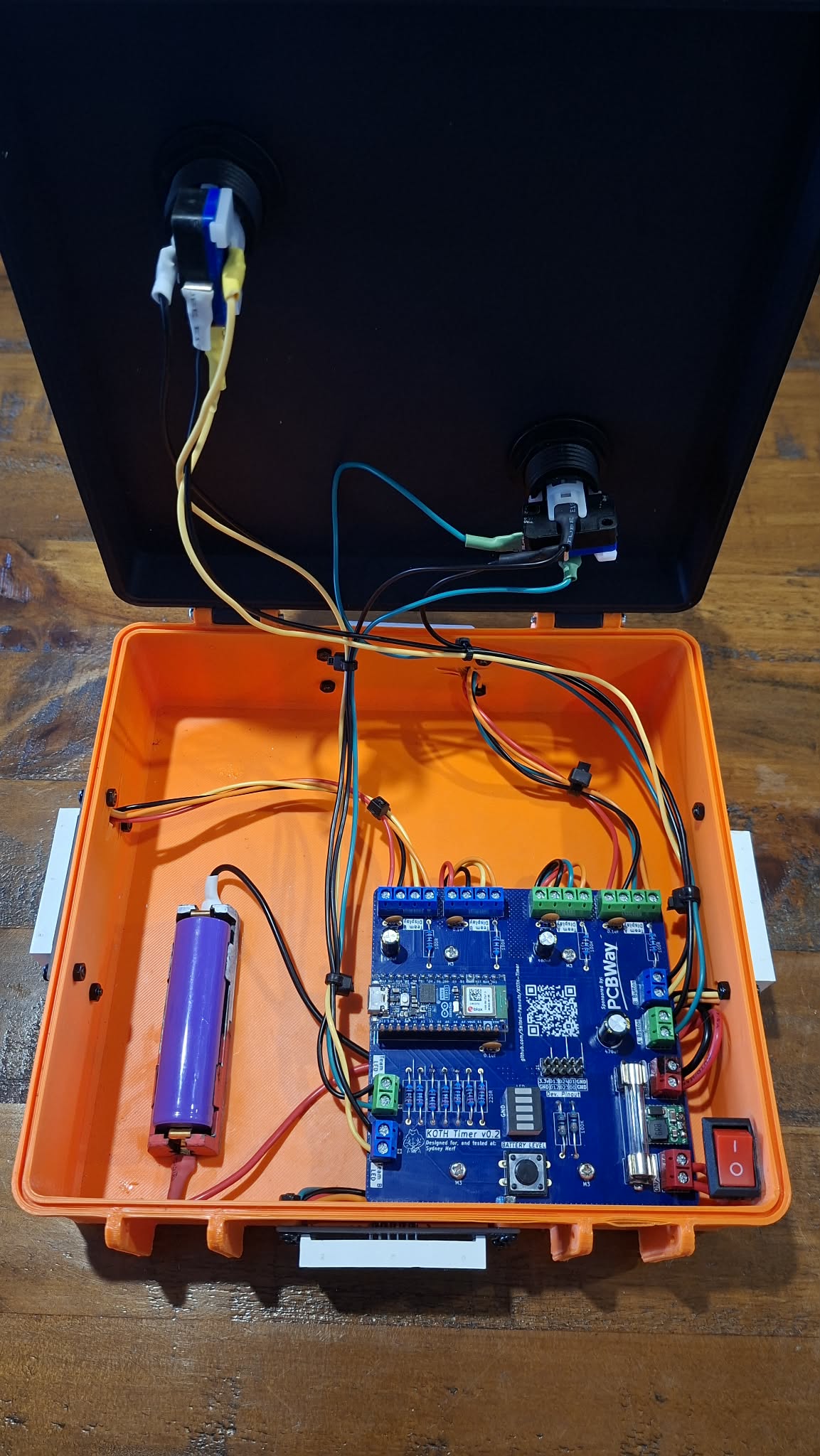
KOTH-Timer Timer internal wiring

Custom PCB

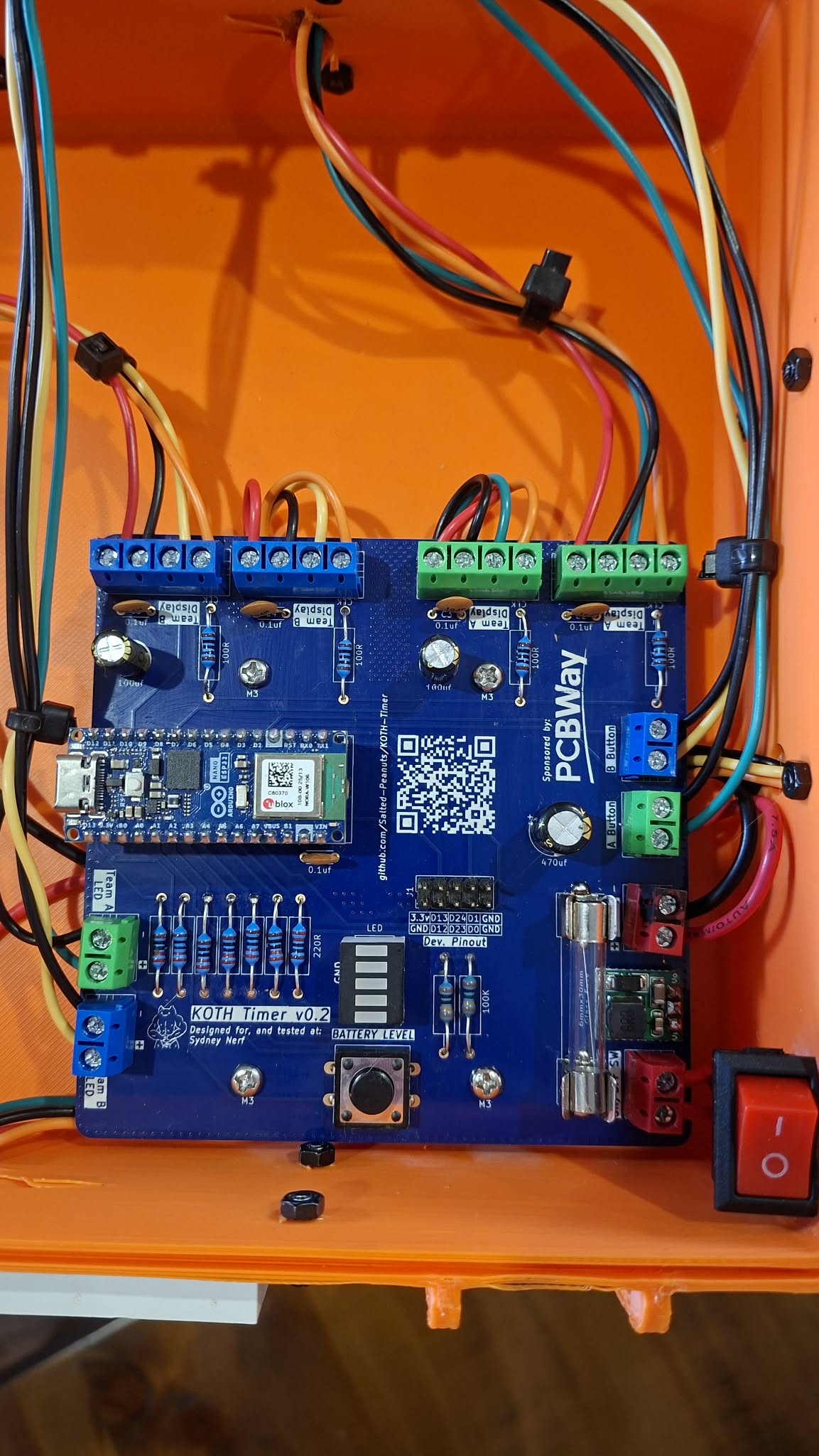
KOTH-Timer Timer custom PCB

Features

  • Two-team King of the Hill timer
  • Physical arcade button controls
  • LED button feedback
  • Four TM1637 4-digit display modules
  • Local ESP32-hosted web interface
  • Phone-friendly referee/admin controls
  • Configurable match duration
  • Configurable team colours
  • Battery voltage display
  • Pause and resume controls
  • Reset lockout to prevent accidental resets
  • Game-over winner display
  • Live referee time adjustment during gameplay
  • Open Wi-Fi network by default for quick event setup
  • Optional Wi-Fi password support
  • No internet required during gameplay

Referee/Admin Connection

The timer creates its own local Wi-Fi network.

text
SSID: KOTH-Timer
Password: none / open network

After connecting, open:

text
http://10.10.10.1

Connection test page:

text
http://10.10.10.1/ping

Some phones may warn that the network has no internet. This is normal. Choose the option to stay connected or use the network anyway.

Optional Wi-Fi Password

The Wi-Fi network is open by default so referees can connect quickly during events.

If you want to add a password, edit the firmware near the top of the code.

Find:

cpp
static const char* AP_PASS = "";

Change it to a password with at least 8 characters:

cpp
static const char* AP_PASS = "kothtimer";

Then upload the firmware again.

Who This Is For

This project is for hobbyists who want to build their own objective timer for games such as:

  • Nerf events
  • Foam flinging games
  • Gel blaster games where legal
  • Airsoft-style objective games where legal
  • Backyard or club-based capture games
  • Custom scenario games

You do not need to be an expert programmer, but you should be comfortable with basic wiring, soldering, and flashing an ESP32.

Basic Hardware Needed

The current build uses:

  • Arduino Nano ESP32
  • 18650 Li-ion cell
  • 18650 battery holder
  • 5 V boost converter
  • Fuse
  • Rocker power switch
  • 2 large arcade buttons with LEDs
  • 4 TM1637 4-digit display modules
  • 5-segment battery indicator
  • Battery display button
  • Resistors
  • Wire
  • Enclosure
  • USB cable for flashing
  • Basic soldering tools

See the docs folder for the BOM, schematic, and full build guide.

Build Guide

Start here:

Build Guide

The build guide covers:

  • Parts required
  • Tools required
  • Power wiring
  • Arduino Nano ESP32 pinout
  • Button wiring
  • Display wiring
  • Battery indicator wiring
  • Firmware upload
  • Wi-Fi connection
  • Event-day testing
  • Troubleshooting

Firmware

The firmware is written for the Arduino Nano ESP32 using the Arduino IDE.

Current recommended firmware:

text
Firmware/KOTH_Timer_v0_3_1/KOTH_Timer_v0_3_1.ino

For Arduino IDE compatibility, the .ino file should be inside a folder with the same name as the sketch.

Hardware Files

Hardware documentation is in the docs folder.

Current files include:

text
docs/BOM.xlsx
docs/BOM.csv
docs/Wiring_schematic.pdf
docs/build-guide.md

PCB Hardware Status

The KOTH Timer now has a tested PCB revision.

PCB revisionStatusRecommendation
v0.1Manufactured and functionally usable through the web UI, but has known TM1637 display reliability issuesReference only / not recommended for new builds
v0.2Manufactured, assembled, and tested with no known faultsRecommended PCB revision

PCB v0.1

PCB v0.1 was the first manufactured PCB revision.

It is functional through the web UI, but some TM1637 displays may show interference, flicker, incorrect segments, or unstable output.

The v0.1 files are kept in the repo for reference, troubleshooting, and comparison, but new builders should use PCB v0.2 instead.

PCB v0.2

PCB v0.2 is the current recommended PCB revision.

It was redesigned based on lessons from v0.1, with improvements around display reliability, local display decoupling, and cleaner TM1637 signal routing.

PCB v0.2 has been manufactured, assembled, and tested with no known faults.

Supported By PCBWay

PCB manufacturing for newer KOTH Timer PCB revisions has been supported by PCBWay.

PCBWay helped support this open-source hardware project by providing PCB manufacturing support while allowing the firmware, design files, known issues, and documentation to remain open source.

Their support made it easier to test real PCB revisions, improve the board design, and share the results back with other builders.

You can check out PCBWay’s PCB manufacturing and assembly services here:

PCBWay

The tested KOTH Timer PCB v0.2 project is available on PCBWay here:

Order / view the KOTH Timer PCB v0.2 project on PCBWay

Thanks to PCBWay for supporting open-source hardware creators and helping this project move from a hand-wired prototype to a tested PCB-based build.

Note: PCBWay supported manufacturing for this project, but the design notes, testing results, known issues, and recommendations in this repository are written independently.

Future Development

Planned future work may include:

  • Improving hardware documentation
  • Adding more photos and wiring diagrams
  • Adding extra game modes beyond King of the Hill
  • Improving the referee/admin interface based on event feedback
  • Exploring a Bluetooth or app-based version if there is enough interest

The v0.3.1 firmware is the current recommended release. It is based on the event-tested v0.3 firmware and includes additional web-interface input fixes.

PCB v0.2 has been manufactured, assembled, and tested with no known faults and is the current recommended PCB revision.

Project Status

This is a hobby project, not a commercial product.

The current firmware has been tested at an event, but builders should still test their own wiring and setup before using the timer in a game.

If you build one, feel free to modify it for your own event rules, enclosure, buttons, battery setup, or game style.

Related Uses

This project may be useful for:

  • Nerf King of the Hill games
  • Foam flinging objective games
  • DIY skirmish game timers
  • Arduino ESP32 game props
  • Capture point timers
  • Referee-controlled event timers
  • Local Wi-Fi game control panels

Licence

This project is released under the MIT Licence.

Parts

35
QtyValueFootprintReferences
7220RResistor_THT:R_Axial_DIN0309_L9.0mm_D3.2mm_P15.24mm_HorizontalR3, R4, R5, R6, R7, R8, R9
3LED_GREENLED_THT:CUSTLEDD5, D6, D7
3MountingHole_3.2mm_M3_ISO7380MountingHole:MountingHole_3.2mm_M3_ISO7380M3, M3, M3
2100KResistor_THT:R_Axial_DIN0309_L9.0mm_D3.2mm_P15.24mm_HorizontalR1, R2
24_Digit_DIsplay (Team_A)TerminalBlock:TerminalBlock_MaiXu_MX126-5.0-04P_1x04_P5.00mmTM1637-A1, TM1637-A2
24_Digit_DIsplay (Team_B)TerminalBlock:TerminalBlock_MaiXu_MX126-5.0-04P_1x04_P5.00mmTM1637-B1, TM1637-B2
10.1uf_C_CapCapacitor_THT:C_Disc_D4.3mm_W1.9mm_P5.00mmC2
118650_CellTerminalBlock:TerminalBlock_MaiXu_MX126-5.0-02P_1x02_P5.00mmBT1
12.5-3A_FuseFuse:Fuseholder_Clip-6.3x32mm_Littelfuse_102_122_Inline_P34.21x7.62mm_D1.98mm_HorizontalF1
1470uf_E_CapCapacitor_THT:CP_Radial_D8.0mm_P5.00mmC1
15v_Step_UpTerminalBlock:TerminalBlock_MaiXu_MX126-5.0-03P_1x03_P5.00mmU1
1Arduino_Nano_ESP32Module:Arduino_NanoA1
1LED (Team_A)TerminalBlock:TerminalBlock_MaiXu_MX126-5.0-02P_1x02_P5.00mmD1
1LED (Team_B)TerminalBlock:TerminalBlock_MaiXu_MX126-5.0-02P_1x02_P5.00mmD2
1LED_REDLED_THT:CUSTLEDD3
1LED_YELLOWLED_THT:CUSTLEDD4
1LOGOcustomfootprints:kicadcatG***
1Push_Switch (Team_A)TerminalBlock:TerminalBlock_MaiXu_MX126-5.0-02P_1x02_P5.00mmSW2
1Push_Switch (Team_B)TerminalBlock:TerminalBlock_MaiXu_MX126-5.0-02P_1x02_P5.00mmSW3
1QR SOTH-Timercustomfootprints:QR SOTH-TimerQR*****
1Rocker_SwitchTerminalBlock:TerminalBlock_MaiXu_MX126-5.0-02P_1x02_P5.00mmSW1
1SW_PushButton_Switch_THT:SW_PUSH-12mmSW4

Questions

How big is the Nerf timer PCB?

It measures 75.9 × 93.5 mm and has 4 copper layers, 1.6 mm thick.

What parts does the Nerf timer use?

35 parts. The full list of its parts is on this page, with links to each part's symbol and footprint where PCBKit's library has them.

Where can I download the Nerf timer KiCad files?

From the Salted-Peanuts/KOTH-Timer repository on GitHub, at the commit this page was made from: the board is PCB/v0.1-display-issues/KiCad_files/nerf timer.kicad_pcb and its schematic PCB/v0.1-display-issues/KiCad_files/nerf timer.kicad_sch. PCBKit opens the board in the browser, with nothing to install.

Can I use the Nerf timer design in my own project?

Its repository publishes it under the MIT licence: you may reuse it on that licence's terms (keep the author's notice, and for a copyleft licence share your changes alike).

More from Salted-Peanuts/KOTH-Timer

1
  • 4 layers100 × 100 mmKOTH V2, the printed circuit board in 3D

    KOTH V2

    Salted-Peanuts/KOTH-Timer

    DIY Arduino Nano ESP32 King of the Hill timer for Nerf, foam flinging, skirmish games, and objective-based events. Includes build guide, firmware, BOM, schematic, and phone referee UI.
    49 parts4MIT

Similar boards

  • 4 layers25.9 × 63.9 mmEasyduino ESP32S3, the printed circuit board in 3D

    Easyduino ESP32S3

    Hanqaqa/Easyduino

    Easily dive into different PCB KiCad designs of the most popular microcontroller devboards

    35 parts755CERN-OHL-P-2.0
  • 4 layers36.8 × 78.6 mmGamepad Left, the printed circuit board in 3D

    Gamepad Left

    tschicki/PS2-Portable

    A custom designed PS2 Portable

    35 parts207MIT
  • 4 layers35.6 × 17.8 mmLofive, the printed circuit board in 3D

    Lofive

    mwelling/lofive

    RISC-V microcontroller board based on SiFive FE310.

    35 parts161
  • 4 layers89 × 93 mmFlasher2, the printed circuit board in 3D

    Flasher2

    clydeshaffer/gametank

    design files for the gametank hardware implementation

    35 parts150
  • 4 layers50 × 60 mmPiCCANTE OBD Dongle, the printed circuit board in 3D

    PiCCANTE OBD Dongle

    Alia5/PiCCANTE

    PiCCANTE is a powerful tool for exploring and reversing CAN busses of vehicles, based on Raspberry Pi Pico (any model)

    35 parts104GPL-3.0
  • 4 layers28.9 × 28.9 mmAgnus, the printed circuit board in 3D

    Agnus

    jbilander/ReAgnus

    A drop-in replacement PCB for the Amiga Agnus chip

    35 parts97CC-BY-SA-4.0
  • 4 layers30.5 × 68.6 mmKick, the printed circuit board in 3D

    Kick

    bread-modular/bread-modular

    Modular Synths for Everyone

    35 parts67MIT
  • 4 layers17.5 × 35 mmKungFuSID, the printed circuit board in 3D

    KungFuSID

    Sgw32/KungFuSID

    Kung Fu SID is a firmware based on Kung Fu Flash which allows SID emulation

    35 parts65