
2 layers24.4 × 24.4 mm
OSO SWAT B1
joeycastillo/Sensor-Watch
A board replacement for the classic Casio F-91W wristwatch
39 parts2.1k

Every version lives side by side in this repo — firmware/v4/, firmware/v5/, cad/stl/v5/ and so on. main is always the latest working state; released versions are marked with git tags, so you can grab any of them:
Macropad is an open-source printed circuit board by saiprashanth802, from the saiprashanth802/ESP32-BLE-Macropad repository on GitHub. It is a 2-layer board of 150.2 × 90.2 mm with 39 parts on 51 nets, routed with 242 tracks and 7 vias.
Its parts include 13 switches, 12 diodes, 8 resistors and 6 connectors. It belongs with the keyboards and input boards of this library.
An open-source, battery-powered wireless BLE HID macro pad built on ESP32 with NimBLE stack. Hand-wired with a custom FDM-printed enclosure, fully self-contained shortcut controller with an on-device UI — no companion app required.

Every version lives side by side in this repo — firmware/v4/, firmware/v5/,
cad/stl/v5/ and so on. main is always the latest working state; released
versions are marked with git tags, so you can grab any of them:
git clone https://github.com/saiprashanth802/ESP32-BLE-Macropad.git
git checkout v4.1 # or v5.0 — see Releases for downloadable zips| Version | Tag | Status | Description |
|---|---|---|---|
| v3 | — | ✅ Complete | 8-button, ST7735 128×160, ESP32-BLE-Keyboard — flagship build |
| v4 | v4.1 | ✅ Stable | NimBLE stack, ghost connection fix, BUILD MODE |
| v4 + Media Remote | — | 🔬 Testing | Wireless AS5600 scroll wheel via ESP-NOW |
| v5 | v5.0 | ✅ Built & Running | 12-key MX matrix, ST7789 240×320, multi-host BLE, robot face, Windows companion app |
| v5.1 | v5.1 | ✅ Current | Local-LLM rewrite menu driven from the pad, wireless encoder puck complete |
Primary portfolio entry. 8-button macro pad with ST7735 display, NimBLE BLE HID, and on-device preset switching with BUILD MODE.
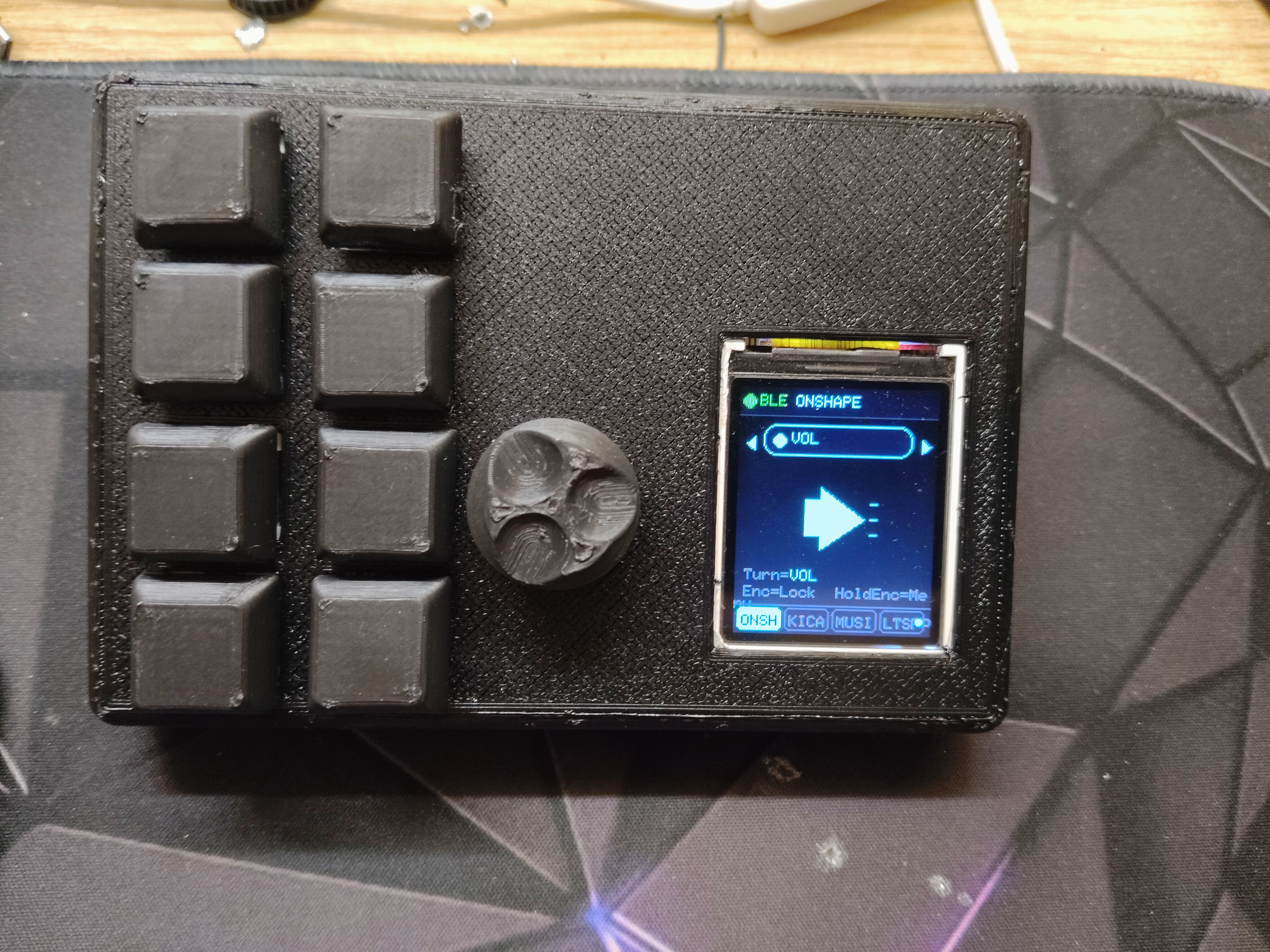 | 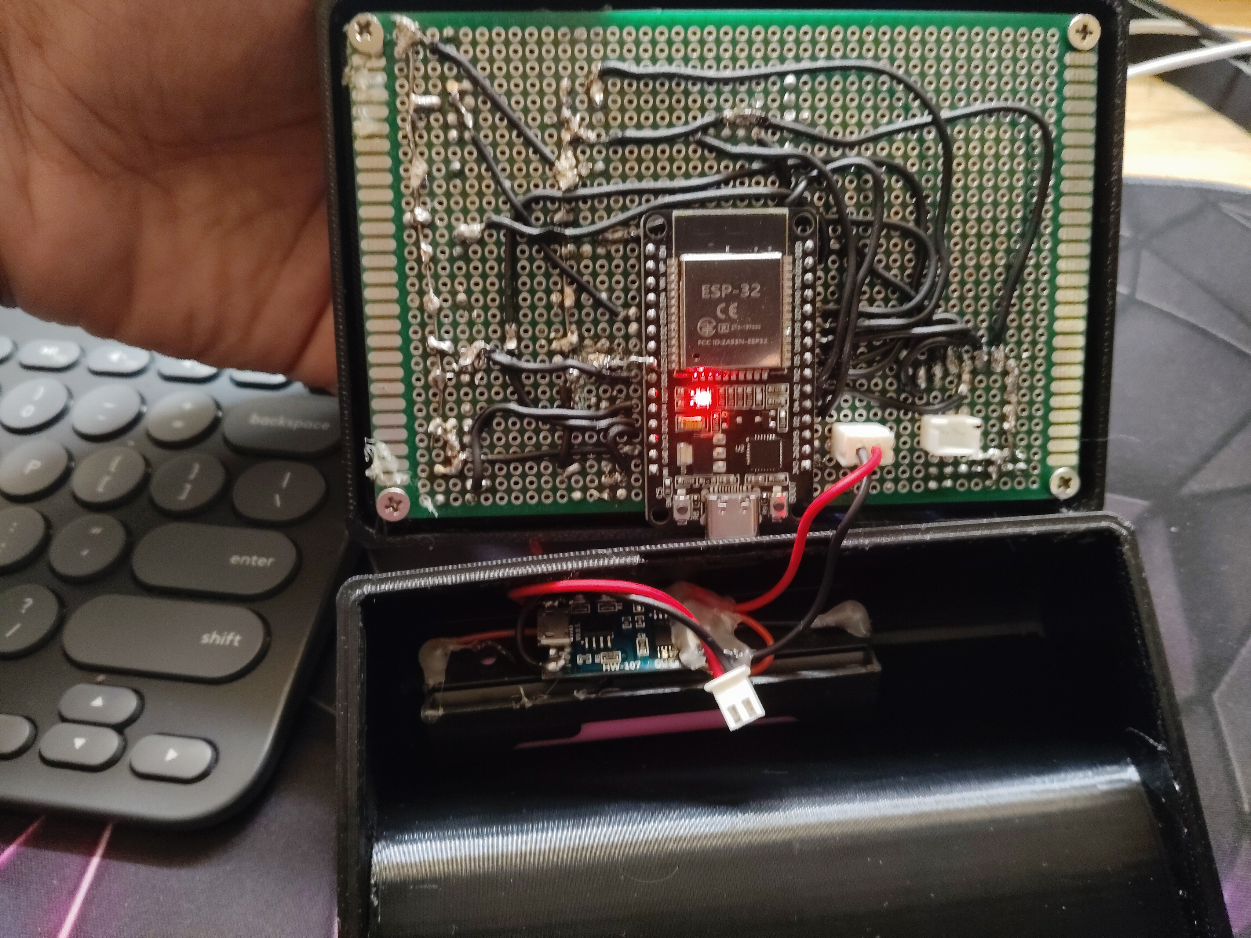 |
| Assembled v3 | Internal wiring |
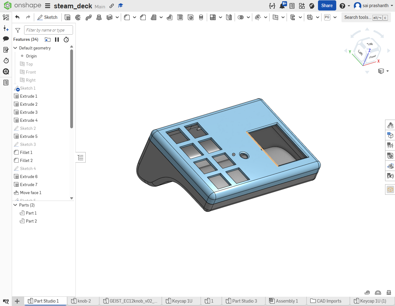 | 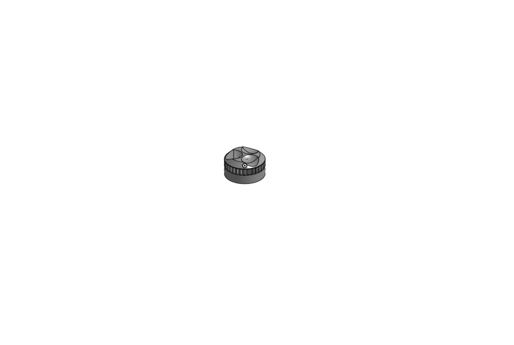 |
| Enclosure CAD | Encoder knob CAD |
| GPIO | Function |
|---|---|
| 14,13,26,25,22,21,35,19 | 8× buttons |
| 2, 4 | Encoder CLK, DT |
| 15 | Encoder SW |
| 5, 17, 16, 12 | TFT CS, DC, RST, BL |
| 23, 18 | SPI MOSI, SCLK |
Migrated to NimBLE-Arduino to fix persistent BLE ghost-connection bug on Windows sleep/wake cycles.
esp_sleep_disable_wakeup_source() before re-arming GPIO wakeup each cycleledcAttach() called on every wake to restore PWM backlightmacropad_v4_nimble_espnow.ino#define ST7735_DRIVER
#define TFT_CS 5
#define TFT_DC 17
#define TFT_RST 16
#define TFT_WIDTH 128
#define TFT_HEIGHT 160
#define TFT_MOSI 23
#define TFT_SCLK 18Standalone wireless scroll wheel using AS5600 magnetic encoder. Connects to v4 macropad via ESP-NOW or directly to PC via BLE HID. Designed for high-resolution smooth scrolling with velocity-based acceleration.
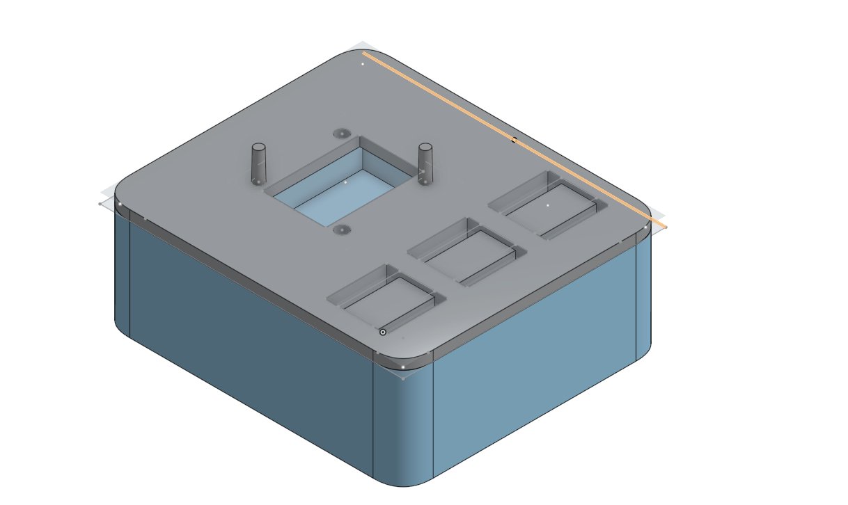 | 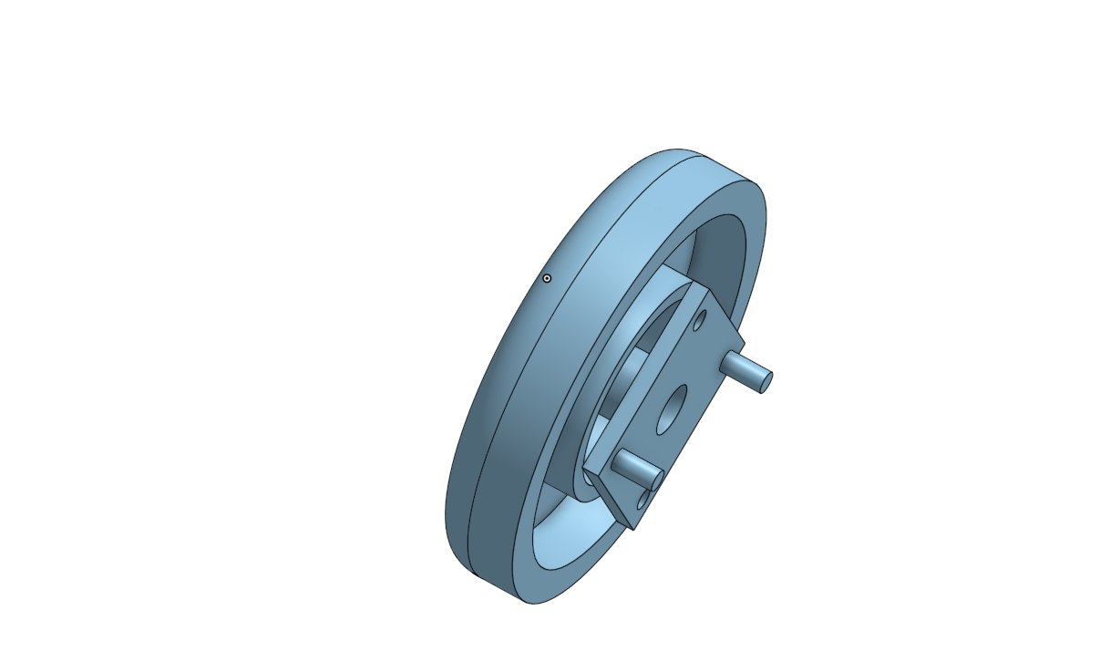 |
| Enclosure CAD | Scroll wheel with bearing mount CAD |
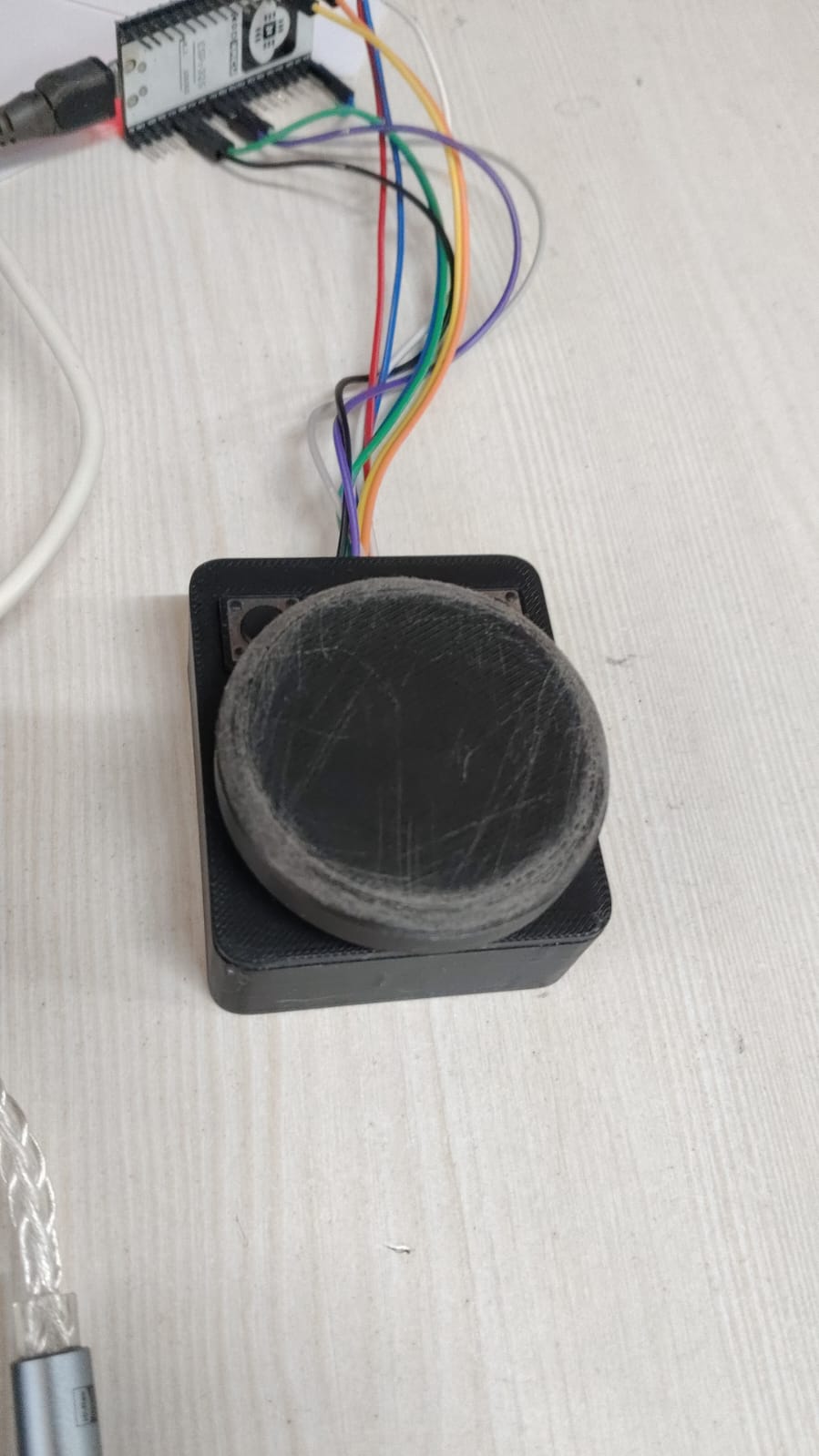
Prototype — printed enclosure with 50mm scroll wheel, AS5600 underneath, wired to NodeMCU ESP32S
| Mode | Description |
|---|---|
| BLE HID | Connects directly to PC as "MediaRemote" |
| ESP-NOW | Sends to v4 macropad which relays via BLE to PC |
| Pin | GPIO | Function |
|---|---|---|
| AS5600 SDA | 21 | I2C data |
| AS5600 SCL | 22 | I2C clock |
| BTN1 Play/Pause | 27 | INPUT_PULLUP → GND |
| BTN2 Next | 26 | INPUT_PULLUP → GND |
| BTN3 Prev | 25 | INPUT_PULLUP → GND |
| LED | 2 | Onboard LED |
Full redesign, assembled and working. 12-key MX mechanical switch matrix (4×3 landscape), ST7789 240×320 IPS display, multi-host BLE with 3 device slots (Logitech Easy-Switch style), a state-reactive robot face with personalities, and a Windows companion app that turns the pad into a Stream Deck.
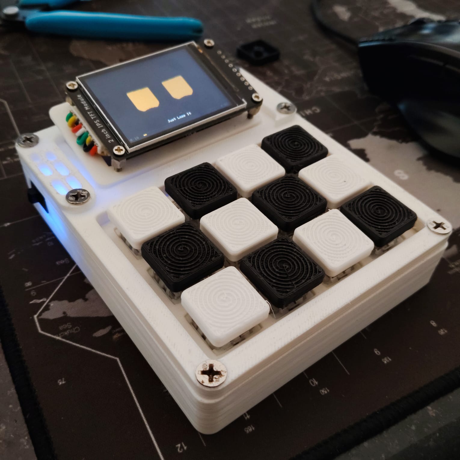 | 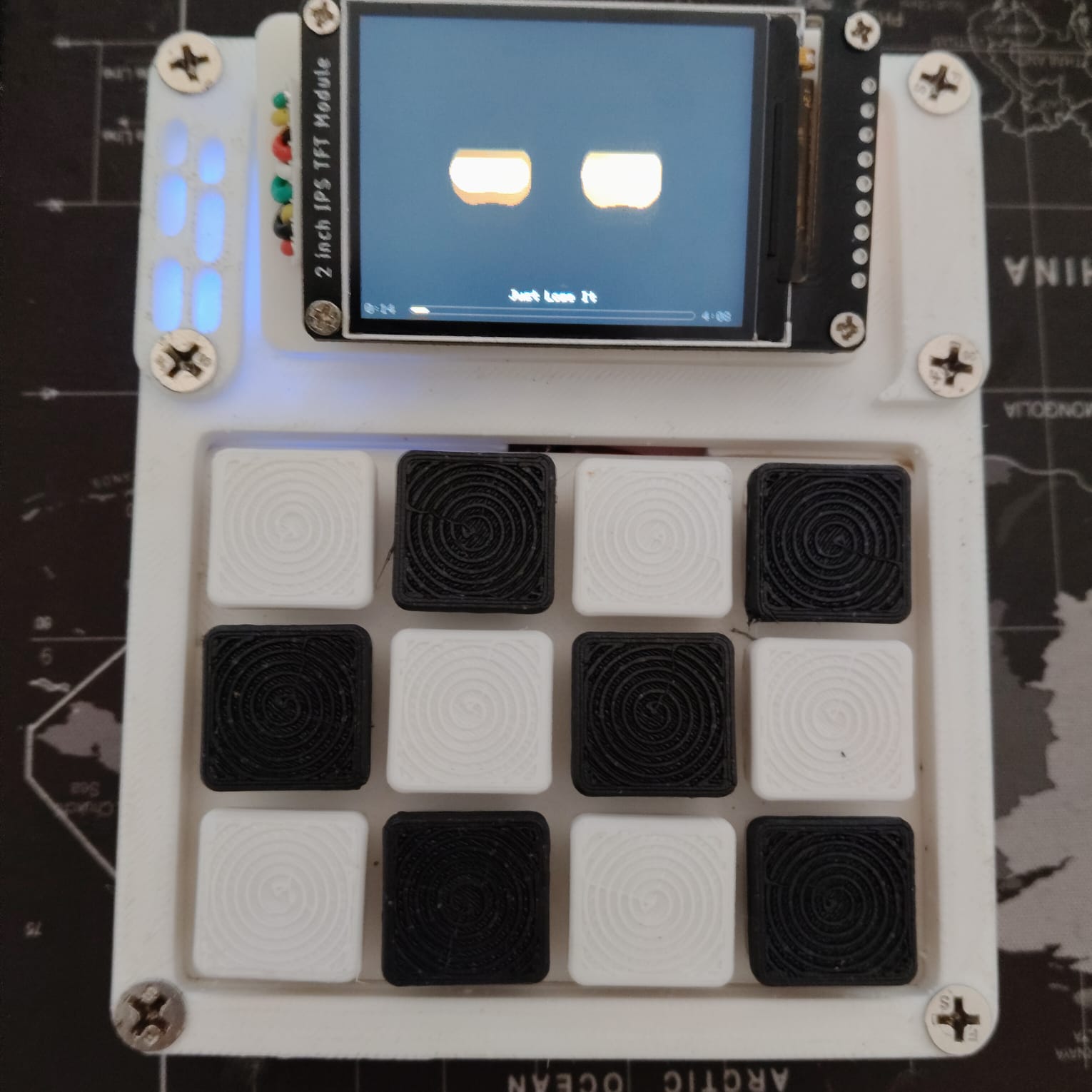 |
| Assembled v5 — printed case, spiral-top keycaps, blue accent lighting | Top-down: 4×3 MX grid and the 2" IPS display |
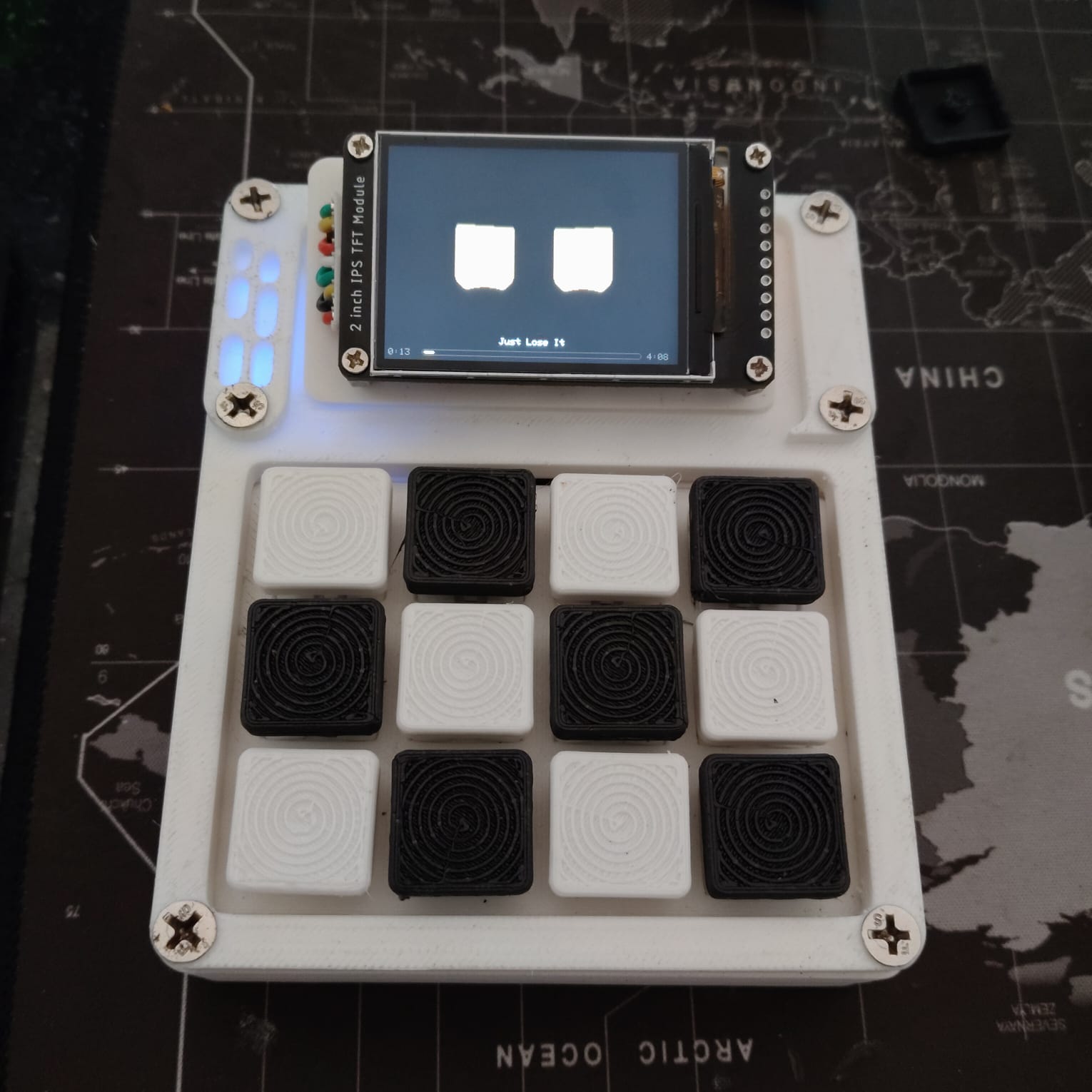
The screen shows the pad's two live features at once: the procedural robot eyes in their default robotic blue, and the now-playing strip — track title with a progress bar and elapsed/total time, streamed from the host by the companion app.
Print files: cad/stl/v5/ — three case parts plus the switch plate.
firmware/v5/macropad_v5.ino (NimBLE 2.x API, single file)styles.json — tune them without a rebuildml/ and docs/FIX_MODEL_FINETUNE.mddocs/REWRITE_MENU.md · Linux setup:
docs/LINUX_REWRITE_SETUP.mdThe pad works standalone. The companion turns it into a Stream Deck: it launches and focuses apps from a key press, streams now-playing to the pad's screen, switches presets to follow the foreground window, feeds the puck a real volume number, and drives the rewrite menu.
MacroPadDeck.Core holds the wire
protocol, profiles and orchestration; MacroPadDeck is WinRT/SMTC/WPF, and
MacroPadDeck.Linux is BlueZ/MPRIS/X11/GTK3companion/README.md — .NET 9 SDK
per platform, the dependencies, pairing, the publish command, and what each failure
in deck.log meansMacroPad-Setup / macropad123, http://192.168.4.1).bin from the browser; it flashes the inactive OTA partition and reboots (safe rollback if it fails)docs/CONFIG_API.md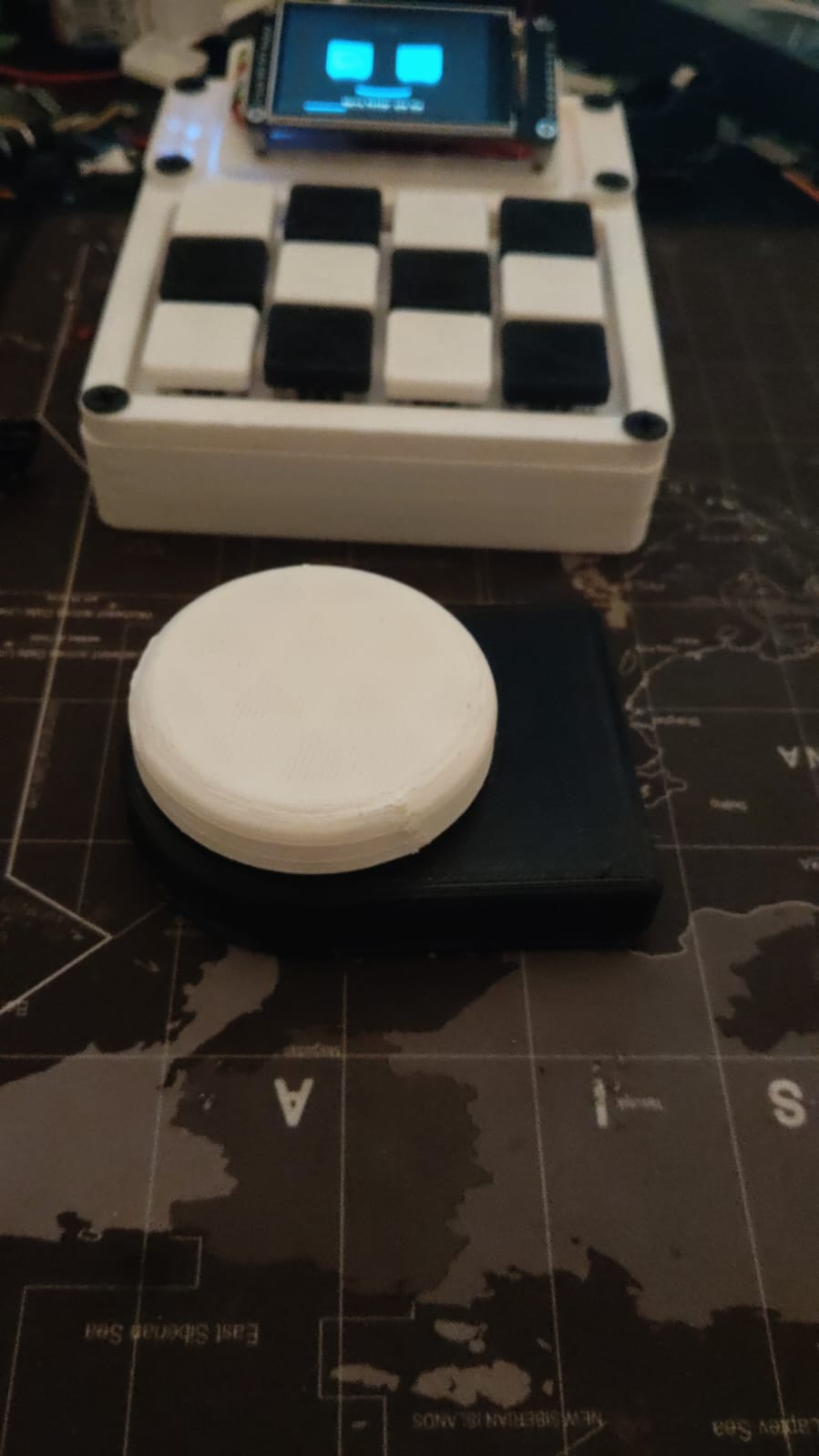 | 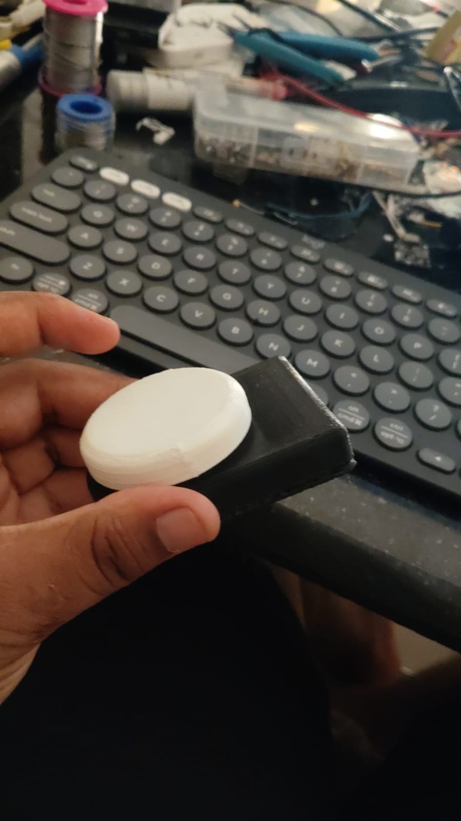 |
| The puck beside the v5 — a separate battery-powered device, no cable between them | 50 mm dial in the two-part printed housing |
hardware/puck_wiring.md · Protocol: docs/PUCK_PROTOCOL.md · Print files: cad/stl/puck/hardware/pin_reference_v5.md)hardware/puck_wiring.md and docs/PUCK_PROTOCOL.md)3D printed plate with elevated ridges as trace isolation guides. A single copper sheet is laid over the entire surface — the ridges act as cutting guides. Scalpel-cut along ridge edges isolates traces. Looks like a real PCB, built from scratch.
| GPIO | Board Label | Function | Notes |
|---|---|---|---|
| 18 | P18 | TFT SCK | SPI clock |
| 23 | P23 | TFT MOSI | ST7789 SDA |
| 5 | P5 | TFT CS | |
| 21 | P21 | TFT DC | |
| 22 | P22 | TFT RST | |
| 19 | P19 | TFT BL | PWM via LEDC |
| 25 | P25 | Matrix Row 1 | Driven LOW to scan |
| 26 | P26 | Matrix Row 2 | Driven LOW to scan |
| 27 | P27 | Matrix Row 3 | Driven LOW to scan |
| 32 | P32 | Matrix Row 4 | Driven LOW to scan |
| 33 | P33 | Matrix Col 1 | INPUT_PULLUP |
| 13 | P13 | Matrix Col 2 | INPUT_PULLUP |
| 14 | P14 | Matrix Col 3 | INPUT_PULLUP |
Zero strapping pins used — clean boot every time, no pull resistors needed for boot. No I2C or encoder switch on the main board — the AS5600 puck is wireless. Full details + diode orientation:
hardware/pin_reference_v5.md.
ESP32-BLE-MacroPad/
├── firmware/
│   ├── v4/macropad_v4_nimble_espnow.ino   — v4 + optional ESP-NOW
│   ├── v5/
│   │   ├── macropad_v5/                   — v5 multi-host firmware + partition table
│   │   ├── puck_encoder/                  — wireless encoder puck (ESP32)
│   │   ├── puck_encoder_8266/             — puck on ESP-12E
│   │   └── User_Setup.h                   — TFT_eSPI config for the ST7789
│   ├── media_remote/                      — BLE + ESP-NOW scroll wheel
│   └── tests/                             — per-peripheral bring-up sketches
├── companion/
│   ├── README.md                          — install / build / run — start here
│   ├── MacroPadDeck.Core/                 — protocol, profiles, controller (net9.0)
│   ├── MacroPadDeck/                      — Windows front-end (WinRT/WPF)
│   └── MacroPadDeck.Linux/                — Linux front-end (BlueZ/MPRIS/GTK3)
├── ml/                                    — the FIX fine-tune lab: data generator,
│                                            eval harness, training configs, runbook
├── cad/stl/                               — print files: v5 case, keycaps, puck
├── hardware/
│   ├── pin_reference_v5.md                — complete v5 GPIO table + diode orientation
│   ├── puck_wiring.md                     — encoder puck wiring
│   ├── kicad/                             — KiCad project + fab gerbers
│   ├── datasheets/                        — ESP-12E
│ └── ESP32_DevKitC_v4.kicad_mod — custom KiCad footprint| Library | Purpose |
|---|---|
| NimBLE-Arduino | BLE HID stack |
| TFT_eSPI | Display driver |
| Preferences | NVS persistent storage |
| Wire | I2C for AS5600 |
| esp_now | ESP-NOW for media remote |
Companion app (see companion/README.md):
| Requirement | Purpose |
|---|---|
| .NET 9 SDK | Builds all three companion projects |
| BlueZ / WinRT | BLE host link to the pad |
| GTK3 + libayatana-appindicator | Linux tray and editor |
| MPRIS / SMTC | Now-playing source |
| Ollama (optional) | Local model behind the rewrite menu |
ledcAttach() after NimBLEDevice::init().CC BY-NC 4.0 — Free to use and modify for personal and non-commercial purposes only. Commercial use requires explicit written permission from the author.
| Qty | Value | Footprint | References |
|---|---|---|---|
| 12 | 1N4148 | Diode_THT:D_DO-35_SOD27_P7.62mm_Horizontal | D12, D13, D14, D15, D16, D17, D18, D19, D20, D21, D22, D23 |
| 12 | SW_Push | Button_Switch_Keyboard:SW_Cherry_MX_1.00u_PCB | SW1, SW2, SW3, SW4, SW5, SW6, SW7, SW8, SW9, SW10, SW11, SW12 |
| 8 | 10k | Resistor_THT:R_Axial_DIN0207_L6.3mm_D2.5mm_P7.62mm_Horizontal | R1, R2, R3, R4, R5, R6, R7, R8 |
| 2 | Conn_01x19 | Connector_PinHeader_2.54mm:PinHeader_1x19_P2.54mm_Horizontal | J4, J5 |
| 1 | Conn_01x02 | Connector_PinHeader_2.54mm:PinHeader_1x02_P2.54mm_Horizontal | J6 |
| 1 | Conn_01x03 | Connector_PinHeader_2.54mm:PinHeader_1x03_P2.54mm_Vertical | J1 |
| 1 | Conn_01x04 | Connector_PinHeader_2.54mm:PinHeader_1x04_P2.54mm_Vertical | J3 |
| 1 | Conn_01x09 | Connector_PinHeader_2.54mm:PinHeader_1x09_P2.54mm_Vertical | J2 |
| 1 | SW_Push | Button_Switch_THT:SW_PUSH_6mm_H4.3mm | SW13 |
joeycastillo/Sensor-Watch
A board replacement for the classic Casio F-91W wristwatch

rusefi/rusefi
rusefi - GPL internal combustion engine control unit

hackclub/OnBoard
💡 Join 1,000 teenagers and make your first PCB with a $100 grant!

ataradov/usb-sniffer-lite
A simple USB sniffer based on Raspberry Pi RP2040

windowsair/wireless-esp8266-dap
CMSIS-DAP compatible wireless debugger for ESP8266/ESP32/ESP32C3/ESP32S3. Optional 40MHz SPI acceleration, etc. 适配多种ESP芯片的无线调试器


lachlanA/eagle-to-kicad
Eagle SCH/LIB to KiCad SCH/LIB ULP conversion script

It measures 150.2 × 90.2 mm and has 2 copper layers, 1.6 mm thick.
39 parts. The full list of its parts is on this page, with links to each part's symbol and footprint where PCBKit's library has them.
From the saiprashanth802/ESP32-BLE-Macropad repository on GitHub, at the commit this page was made from: the board is hardware/kicad/macropad.kicad_pcb and its schematic hardware/kicad/macropad.kicad_sch. PCBKit opens the board in the browser, with nothing to install.
Its repository states no licence, so its author keeps all rights: ask saiprashanth802 before reusing the design.