
2 layers35 × 14 mm

 saimh-ee/PPG-Heart-Sensor
A custom KiCad PCB developed as an extension of a UBC ENGR 352 Microelectronics II photoplethysmography (PPG) heart-rate sensing project.
PPG heart rate sensor is an open-source printed circuit board by saimh-ee, from the saimh-ee/PPG-Heart-Sensor repository on GitHub. It is a 2-layer board of 117 × 31 mm with 44 parts on 21 nets, routed with 207 tracks and 0 vias.
It is built around the MCP601-I/P. Its parts include 17 resistors, 6 capacitors, 4 ICs, 3 transistors and 2 diodes. It belongs with the sensors and measurement boards of this library.
A custom KiCad PCB developed as an extension of a UBC ENGR 352 Microelectronics II photoplethysmography (PPG) heart-rate sensing project. The original course work focused on simulation and breadboard prototyping, and this PCB was designed to turn that work into a cleaner hardware implementation.
This project is based on a PPG sensing approach that uses an infrared emitter and photodiode to detect pulse-related changes optically. The original course work focused on simulation and breadboard prototyping, while this repository focuses on the PCB design, supporting simulation files, fabrication outputs, and project visuals.
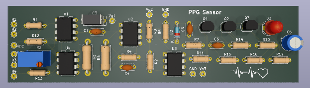
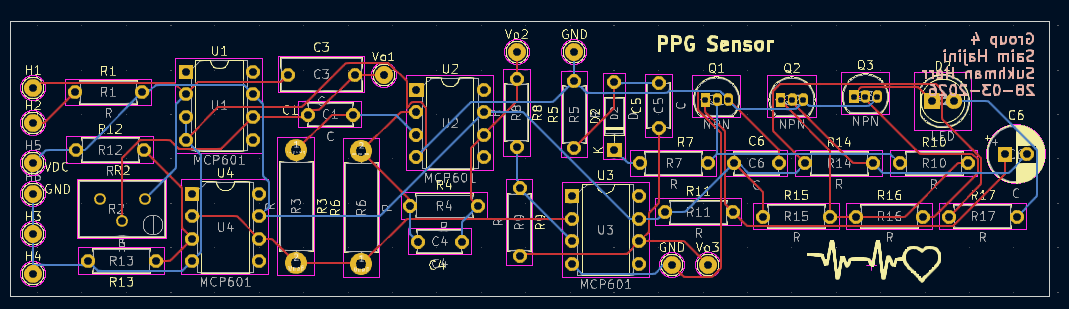
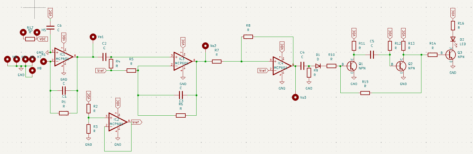
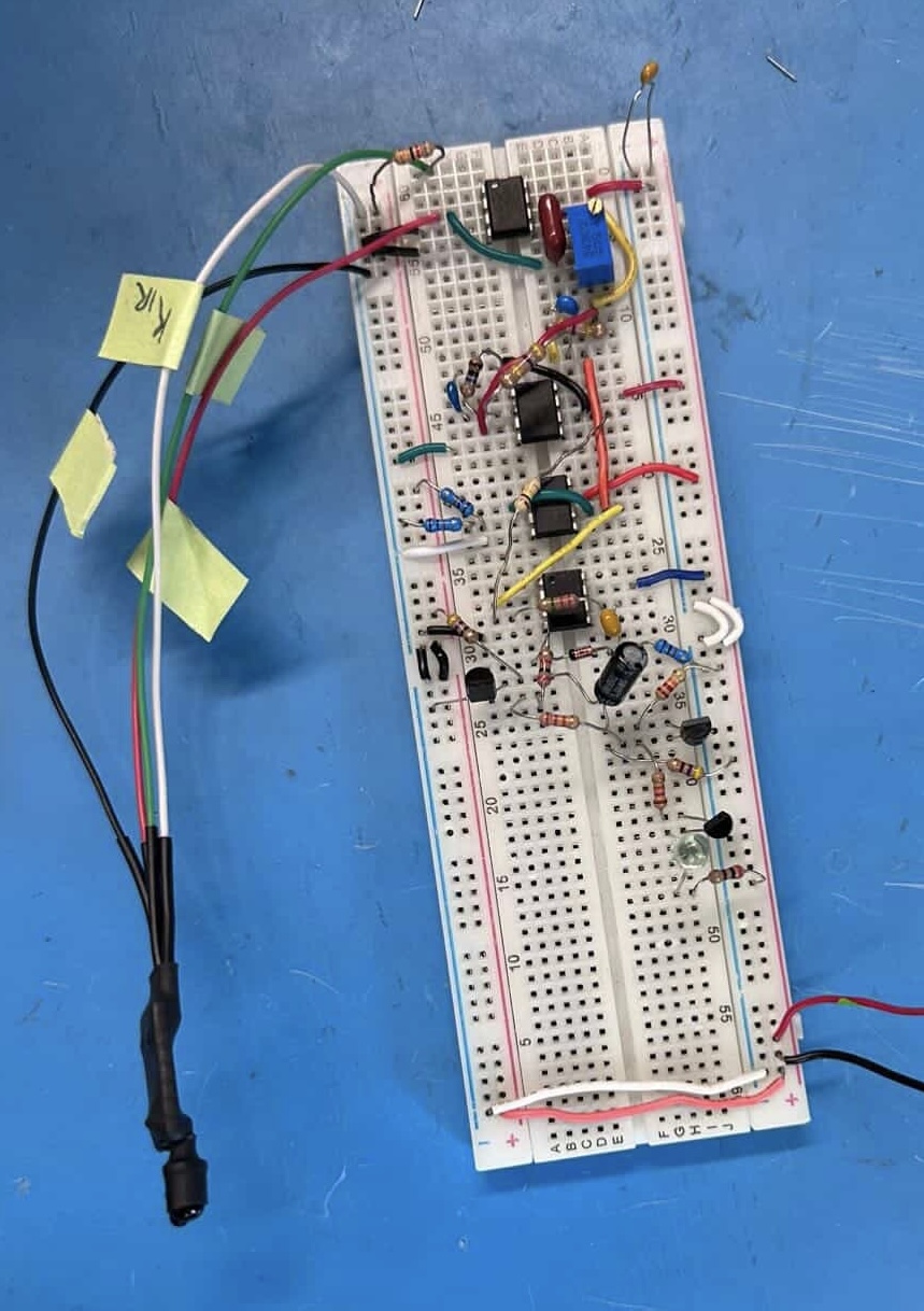
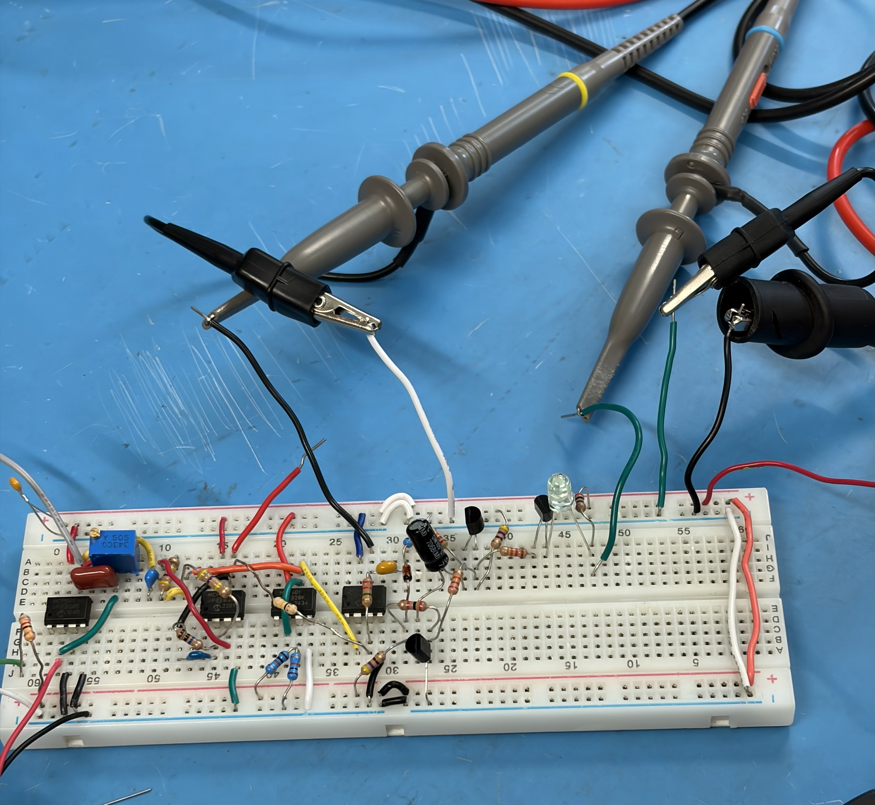
This repository documents both the original prototype stage and the PCB design work completed afterward. The PCB was created as an extra step beyond the base lab requirement in order to package the design into a more polished hardware form.
| Qty | Value | Footprint | References |
|---|---|---|---|
| 14 | R | Resistor_THT:R_Axial_DIN0207_L6.3mm_D2.5mm_P7.62mm_Horizontal | R1, R4, R5, R7, R8, R9, R10, R11, R12, R13, R14, R15, R16, R17 |
| 11 | MountingHole_Pad | TestPoint:TestPoint_THTPad_D2.0mm_Drill1.0mm | GND, GND, H1, H3, H3, H4, H5, H6, Vo1, Vo2, Vo3 |
| 4 | MCP601 | Package_DIP:DIP-8_W7.62mm | U1, U2, U3, U4 |
| 3 | C | Capacitor_THT:C_Disc_D5.0mm_W2.5mm_P5.00mm | C1, C5, C6 |
| 3 | NPN | Package_TO_SOT_THT:TO-92_Inline | Q1, Q2, Q3 |
| 2 | R | Resistor_THT:R_Axial_DIN0411_L9.9mm_D3.6mm_P12.70mm_Horizontal | R3, R6 |
| 1 | C | Capacitor_THT:CP_Radial_D6.3mm_P2.50mm | C6 |
| 1 | C | Capacitor_THT:C_Rect_L9.0mm_W3.6mm_P7.50mm_MKT | C3 |
| 1 | C4 | Capacitor_THT:C_Disc_D5.0mm_W2.5mm_P5.00mm | C4 |
| 1 | D | Diode_THT:D_DO-35_SOD27_P7.62mm_Horizontal | D2 |
| 1 | LED | LED_THT:LED_D5.0mm | D2 |
| 1 | LOGO | LOGO | G*** |
| 1 | R | Potentiometer_THT:Potentiometer_Bourns_3299Y_Vertical | R2 |

kpatrykEIT/DDS_generator_ATmega32u4
Programmable periodic waveform generator based on the ATmega32U4 microcontroller and a DAC

MadsRudolph/62768-energy-system
Team project for 62768 Electrical Energy Systems (DTU, June 2026, 3-week course). We design and build a complete electrical energy system per the course requirement spec (Kravspecifikation), from idea to a working…


It measures 117 × 31 mm and has 2 copper layers, 1.6 mm thick.
44 parts, built around the MCP601-I/P. The full list of its parts is on this page, with links to each part's symbol and footprint where PCBKit's library has them.
From the saimh-ee/PPG-Heart-Sensor repository on GitHub, at the commit this page was made from: the board is Hardware/PPG_heart_rate_sensor.kicad_pcb and its schematic Hardware/PPG_heart_rate_sensor.kicad_sch. PCBKit opens the board in the browser, with nothing to install.
Its repository states no licence, so its author keeps all rights: ask saimh-ee before reusing the design.